1
$\begingroup$

I need to know if something will burn up beforehand I plug all the circuits:

  • Ramps 1.6+
  • Arduino Mega 2560
  • PSU 12 V, 15 A
  • 2 TMC2130 V3.0 Stepper motor driver
  • 2 Stepper motors 17hs3401

Driver Potentiometer

The driver has a potentiometer to change the voltage that is giving to the motors. Range of Vref values:

  • Default: 1 V (±0.2)
  • MAX: 2.4 V
  • MIN: 0 V

As one person answered me in another question, I would need 3.2 V to make the motor work well (2. Ω * 1.3 A = 3.2 V). As the driver just can offer 2 A I assume that the speed will be lower and the driver will be warmer because the motor will drain more current.
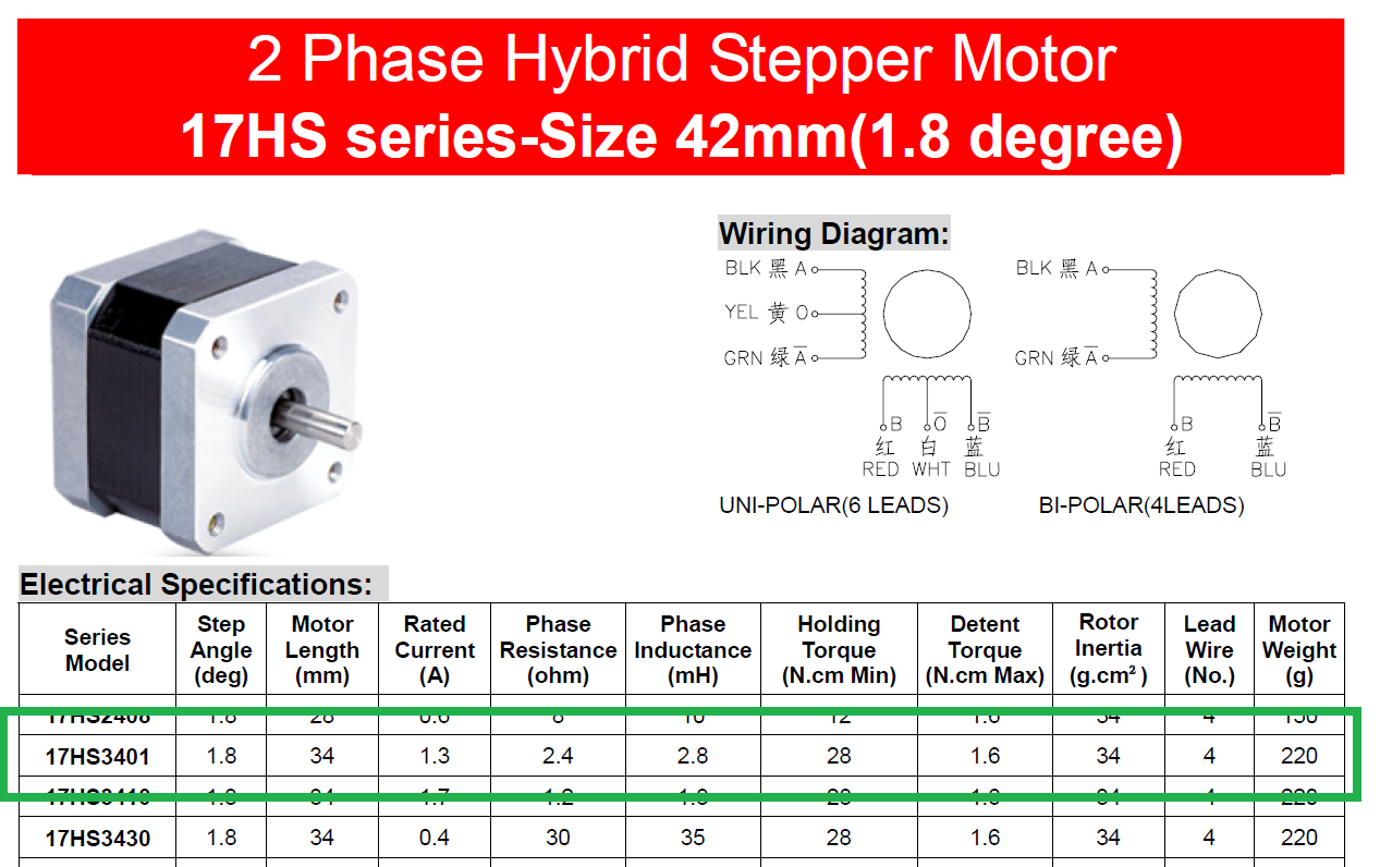
stepper_motor

Marlin Current Configuration

There is a file in the Marlin firmware (Configuration_adv.h) where I can set the current that the driver is going to give to the motors. I do this to calculate the current in the motor XCURRENT = 1300 mA x sqrt(2) = 1838.5 mA and set the value in the file

    #if AXIS_IS_TMC(X)
        #define X_CURRENT       1838.5      // (mA) RMS current. Multiply by 1.414 for peak current. Default 800
        #define X_CURRENT_HOME  X_CURRENT   // (mA) RMS current for sensorless homing
        #define X_MICROSTEPS    16          // 0..256
        #define X_RSENSE        0.11
        #define X_CHAIN_POS     -1          // <=0 : Not chained. 1 : MCU MOSI connected. 2 : Next in chain, ...
    #endif

Possible problems

What I am going to do is to set the drivers potentiometer to the maximum and check what happens. And I will also set the current in the Marlin to 1838.5mA

As the drivers have less voltage to give to the motors, are my drivers going to burn because they will have to give more current for a long period of time? Or will the stepper motors burn because they won't get enough current or voltage?

I also found some other possible problems in this other answer

If the current is too high, you lose the linearity of micro-stepping. If the highest current exceeds the maximum, then the highest current micro-stepping positions will collapse on each other.

If you are within the specs of the motors, there are no motor-related problems caused by higher currents.

But other problems can be caused by increasing the current. The current must be within the capacity of the motor drivers and their heat sink. If the drivers overheat, many will simply shut off, causing the motors to not move when they should, which will appear as misalignment on X, Y, or Y.

This other person also told me

you set the power level for the TCM2130 to more than 50 % then it will overheat. However, it may only do so when running at low speed. I doubt it will overheat if running at a high speed

The TMC2130 drivers can tolerate a motor operating current 1.2 A (peak 2 A). I am setting the maximum to 1838.5 mA (that's Okay) and the motor RMS is 1.3 A (more than 1.2 A). Will these settings overheat the driver?

Question

Will I have any of these problems with the configuration I have set above? Will the TMC2130 overheat?

Update 22 April

My chip is the TMC2130-LA. Then, to calculate the X_CURRENT value:

Imax = 1.2 A            # max current available in the controller                      
Irms = Imax / 1.41 = 0.851
X_CURRENT = 90% Irms = 0.851 * 0.9 = 0.766 = 766 mA   # 90% for safety
$\endgroup$

1 Answer 1

3
$\begingroup$

The driver has a potentiometer to change the voltage that is giving to the motors.

[...]

As one person answered me in another question, I would need 3.2 V to make the motor work well (2. Ω * 1.3 A = 3.2 V).

You are misunderstanding that answer and what the potentiometer does. The potentiometer does not control the voltage going to the motors. It makes no sense to compare this voltage to the rated voltage of the motor. The potentiometer controls the current going to the motor, with a potentiometer voltage of 0V corresponding to 0% of the driver's current, and a potentiometer voltage of 2.5V corresponding to 100%. The documentation of your driver is a bit unclear but it looks like the maximum peak current is 1A per phase or 0.7A RMS (per phase).

There is a file in the Marlin firmware (Configuration_adv.h) where I can set the current that the driver is going to give to the motors.

This only works if the driver is set to SPI mode, otherwise the setting is ignored. To enable SPI mode you need to remove the jumper resistor labeled "SPI" mode and make connections to the long pins sticking out the top of the driver. This configuration option overrides the current setting set by the potentiometer.

What I am going to do is to set the drivers potentiometer to the maximum and check what happens. And I will also set the current in the Marlin to 1838.5mA

That's not such a good idea. It would be wiser to set the potentiometer relatively low, and increase it just enough so that the motors do not skip steps.

As the drivers have less voltage to give to the motors, are my drivers going to burn because they will have to give more current for a long period of time?

No, because the drivers do not have "less voltage to give to the motors". They don't work that way. They are constant current drivers.

Or will the stepper motors burn because they won't get enough current or voltage?

No. The only thing that could cause the motors to burn is (far) too much current or voltage. This will never happen because your drivers will burn up before the motors ever would.

Keep in mind that in the question you linked to, one answer is more detailed than you can reasonably understand with your level of electronics knowledge, and the other answer is completely wrong.

Summary

  • The current setting in configuration_adv.h is irrelevant unless you have enabled SPI (but I doubt that you have)

  • Do not start out with the potentiometer set to maximum

  • Everything will be fine. The motor can handle more current than the driver can ever deliver. The driver you have is configured so that it can never exceed its rated current.

Regarding your update

Yes, if you are using SPI current control then the potentiometer is ignored.

The TMC2130 can handle 1.2A RMS per coil, though the datasheet notes that more than 1A RMS per coil requires special attention to heat dissipation (the small breakout PCB probably does not have great thermal properties).

Your calculation is overly conservative because it treats the 1.2A figure as peak current when RMS current is meant. You do not need to divide by $\sqrt{2}$ to convert to RMS because the figure already is RMS.

$\endgroup$
0

You must log in to answer this question.

Not the answer you're looking for? Browse other questions tagged .