6
$\begingroup$

I have a Reprap Guru Prusa i3 v2 3D printer. Here is a link to the 192 MB manual. And here is the link to the resources page for the Reprap Guru. Page 58 of the manual discusses electronics.

I purchased a 5.5 W laser from an online resource (AliExpress). It has its own controller module. It has one connector with 3 pins

  1. 12 V
  2. Gnd
  3. PWM

I want to now connect the laser module in-place of the 3D printer nozzle. I have been able to install it physically, but not sure how to connect it to the Reprap Guru Prusa i3 board.

I am not an electrical engineer, but I am capable of connecting wires with clear instructions. Any pointers on how to connect this module to the 3D printer board is appreciated.

Updates:

  1. The board of my 3D printer is an Arduino Mega 2560 board.
  2. I have been able to power the laser on using the fan connections and it can burn stuff (so it works). I have connected to the D9 pins
  3. Now need to figure out where to connect the PWM from the laser module to the Arduino Mega 2560 board
$\endgroup$
3
  • 3
    $\begingroup$ Ensure that you have correct safety glasses for the frequency of your laser diode. There are many versions of laser safety glasses, but you must match your laser to the glasses, when using such a high power diode laser. Ensure also that anyone within view of the machine has these glasses as well. Reflections from a five watt laser will destroy tissue without the awareness of the victim. You may already be aware of this consideration. $\endgroup$
    – fred_dot_u
    Commented May 18, 2019 at 0:53
  • $\begingroup$ Yes glasses are covered. Have gotten the setup work without PWM. Need that to achieve grayscale $\endgroup$
    – codeNinja
    Commented May 18, 2019 at 3:32
  • 1
    $\begingroup$ The ideal would be to change out all the plexiglass in the enclose with the equivalent of the safety glasses for the frequency of you laser. Otherwise, you need to restrict access during laser operation. $\endgroup$
    – Perry Webb
    Commented May 18, 2019 at 13:23

1 Answer 1

7
$\begingroup$

By connecting to the D9 output header (see RAMPS 1.4 shield schematic below) you only have 2 wires that represent a scheduled load and ground. You actually need to connect the positive (red) lead to the power supply 12 V and the negative (black) lead to the ground. The third wire (usually a different color) needs to be connected to the actual D9 in your example; note that this one is connected to the MOSFET! And as such not readily available, it is far more easy to use an other free pin.


Just use the PWM pin (attached to the MOSFET) of the print cooling fan (that schedules the MOSFET), you can then schedule the laser power with G-code M106, e.g. M106 S127 to select half the power (S255 would be max power). Alternatively, and probably a much better solution is that you can use any free (but exposed) pin of your microprocessor; you can set the value of that pin using G-code M42.

M42 switches a general purpose I/O pin. Use M42 Px Sy to set pin x to value y, when omitting Px the LEDPIN will be used.

The only electrical wiring you need to do is to attach a wire (solder or connect to a header) to bundle that with a power and ground wire and route that to the laser module.

Note that the PWM pins of the Mega are numbered D2 through D13. Also, D44, D45 and D46 are also PWM capable. Checking the RAMPS 1.4 (the board/shield of the Reprap Guru) pinout, you will see that D8, D9 and D10 are used for the MOSFETs (and as such not easily available and would require soldering). E.g. D2 and D3 are used by the X max/min endstops (note that most printers don't use an X-max, so pin D2 may be free on your machine).

For your purpose, any of the following pins can be used: D2, D4-7, D1112-13 and D44-46.

Best option would be the D11 pin (on second thoughts, D4 might be a much better option as the timer associated with PWM on pin D11 is internally used in Marlin for generating interrupts); it has a pin you can connect to the SERVO header pin.

The image shows the location of the pins:
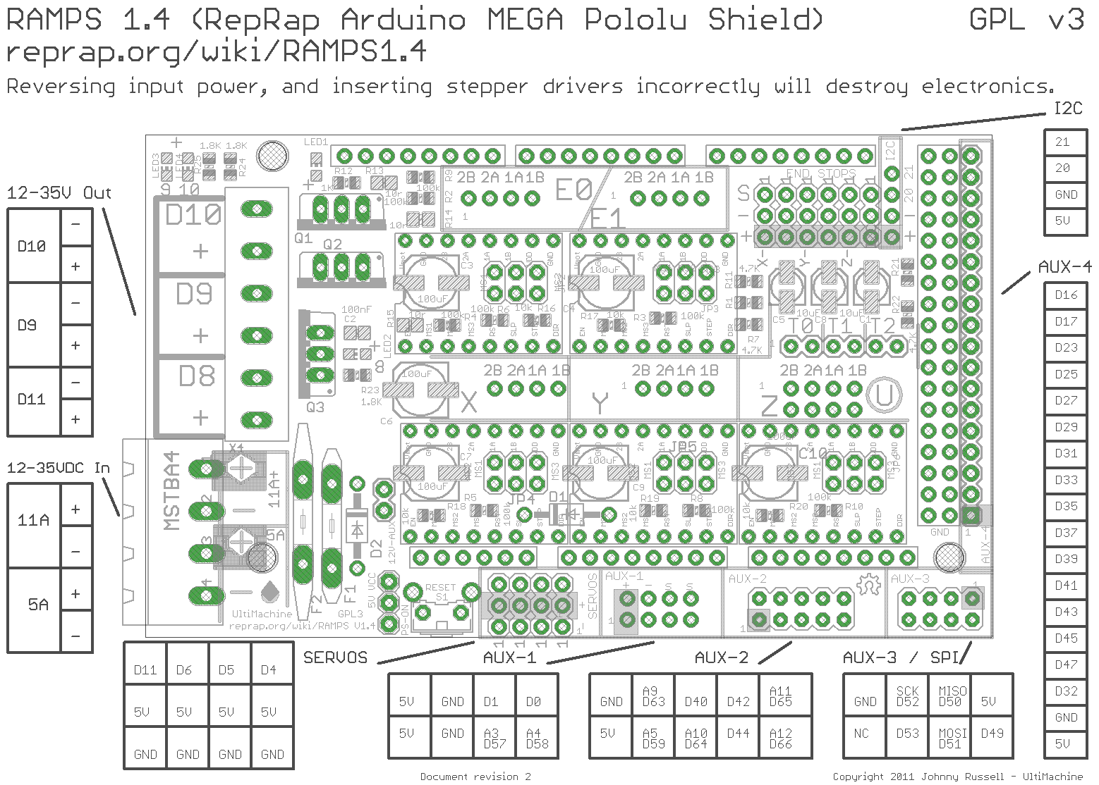
RAMPS pin layout

An example to connect a laser module is seen in this image: Wiring laser module to RAMPS D4 pin on AUX2
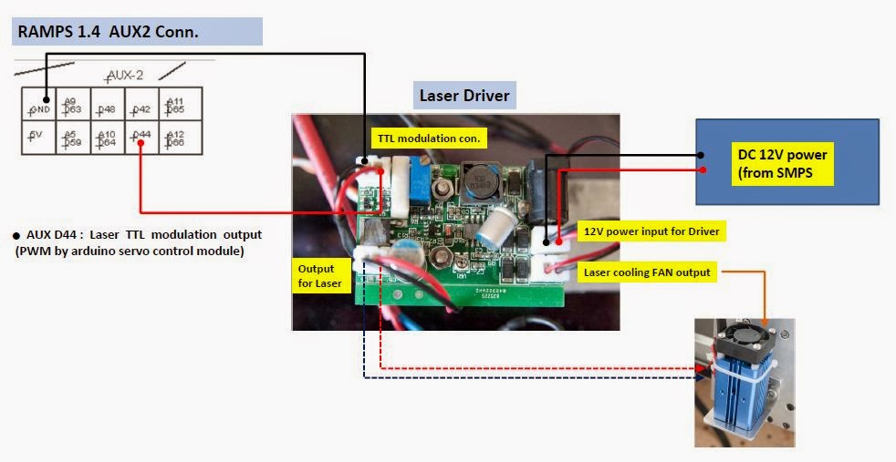
$\endgroup$
4
  • $\begingroup$ Great details and I can confirm the the board in your image matches what I have. Are you referring to D2, D4-7, D11-13 and D44-46? Also seems like the cooling fan was only connected to D9 (power), so I am not sure how it's PWM connection can be leveraged her $\endgroup$
    – codeNinja
    Commented May 18, 2019 at 10:49
  • 1
    $\begingroup$ There are plenty of other pins to use, just look them up in the schematics, you can edit the schematic yourself if you want to encircle them, but that is not necessary for answering the question. Do not use the +/- under D9, you could use the pin that is attached to the MOSFET, but don't bother, there are plenty more free pins to use! The answer explains what you can use. I would not solder if I were you, but you could, it would work! Best option would be the D11 pin; it has a pin you can connect to the SERVO header pin. $\endgroup$
    – 0scar
    Commented May 18, 2019 at 12:23
  • $\begingroup$ Okay that helps. Clarifying my understanding. (1) connect the PWM wire from the laser to D11. (2) connect the power wires to 5A power supply in pins on the ramp 1.4 board. $\endgroup$
    – codeNinja
    Commented May 18, 2019 at 13:04
  • 2
    $\begingroup$ I was able to control the laser by sending the M42 P11 S0 and M42 P11 S255 codes. The laser does not turn on with any other SXX value. Saw this article (reprap.org/forum/read.php?147,651203) which says that D11 is being used by a timer. Changed to pin D4 and am able to control any power level by sending M42 P4 SXX. Now testing if printing in grayscale actually works, the purpose behind the question. $\endgroup$
    – codeNinja
    Commented May 19, 2019 at 22:46

You must log in to answer this question.

Not the answer you're looking for? Browse other questions tagged .