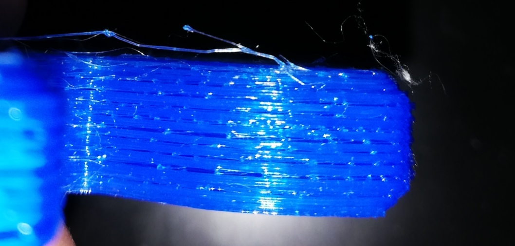
I see you've already accepted an answer, but based on your comments I think you have some misunderstandings of the topic which are worth clarifying as part of answering this question.
0.2125 layer height (+1/4 microstep) and doing all the movements in absolute movements instead of relative forced the result, as the target heights were as a result at 0.2125 mm (for the stepper that's effectively a 0.2 mm), 0.425 (0.4), 0.675 (for the stepper that's, depending on rounding or truncting, 0.6 or 0.7), 0.9 (here they are both 0.9) and so on.
It sounds like your understanding is that the stepper driver is "rounding"/"truncating" to Z positions that are multiples of 0.1 mm. Perhaps that's based on the LCD status display of the Ender 3's firmware, which is based on Marlin 1.0 or something around that version, and shows current coordinates rounded or truncated (I forget which) to one decimal place. This does not have anything to do with the positioning limitations of the actual machine; it's just bad user interface design.
The actual firmware position is translated from the floating point value in the gcode to the nearest step/microstep that the stepper driver can represent. With full steps being 0.04 mm, microsteps are 0.0025 mm (1/16 of a step). All of these positions are "exact" in a logical sense, but of course subject to physical limits of the mechanical parts and accuracy of microstepping. On the topic of microstepping accuracy, you should read How Accurate Is Microstepping Really? Most if not all models of the Ender 3 have A4988 stepper drivers, one of the chips reviewed in that article. But the important part is that there's no rounding/truncation to whole steps taking place. Rather, the stepper driver is trying to position the motor in between whole steps by balancing the magnetic fields pulling it in each direction, with the goal of producing a linear interpolation between the two adjacent full steps. How well it does this is a matter of the quality of the stepper drivers and the load on the motor.
Back to your test, your layer height of 0.2125 mm is not one step plus 1/4 microstep. It's 5 steps (5 * 0.04 mm) plus 0.0125 mm which is 5 microsteps. This is probably a decent test - 5 is 1 mod 16, so you'll end up with a period-16 cycle of microstep positions, at 5, 10, 15, 4, 9, 14, 3, 8, 13, 2, 7, 12, 1, 6, and 11 microsteps mod the whole step. This is pretty close to a period of 3, so you might expect to see some irregularity from poor microstepping accuracy that looks periodic every 3 layers, or you might see it repeating only every 16 layers (every 3.4 mm). But regardless I would not expect delamination problems from this. I think there's another serious extrusion problem behind the photo in your question, and you should probably open a new question about what it might be.
