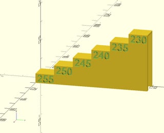
When you slice an STL of a heat tower, you need to tell the slicer that you need a different temperature at a certain level and maintain that new temperature until another change is requested.
The way I usually do it is by using a post processing script in Ulltimaker Cura, but you can do it yourself quite easily by changing the G-code file manually.
To get it to work in Ultimaker Cura is to:
- open a heat tower STL model onto the virtual build plate,
- choose the correct print settings, e.g. fan speed, print speed, layer thickness, etc.,
- now navigate from the main top menu bar
Extensions -> Post Processing -> Modify G-Code,
- select
Add a script and choose ChangeAtZ,
- you now are presented with an option (called
Trigger) that you can change options at either a certain Height or at a certain Layer No. number, you decide what you want to use based on the model and layersize used, but height can be chosen safely when you know the height changes in the heat tower model
- set a certain height at which you want to change the print properties by specifying a height in option
Change Height,
- now put a checkmark in
Change Extruder 1 Temp (be sure that the box Behavior is set to Keep value so that it maintains this value until you specify otherwise, else it is only valid for a single layer),
- a new input box will be presented to you where you can enter the value of the extruder,
- repeat this adding of "changes at certain height" e.i. instances of
ChangeAtZ until you have specified all the temperatures for all the levels
- now slice the model (if not done automatically) and save the G-code file for printing.
If you look into the generated G-code file (the snippet below is taken from a G-code file for an Ultimaker 3) you will see that the post processing script will add extra lines in your G-code file. E.g. the following snippet shows you 2 changes of temperature, one at 5 mm (extruder 1 @ 250 °C), the other at 10 mm (extruder 1 @ 245 °C):
...
;LAYER:48
G0 X93.4 Y132.161 Z5
;ChangeAtZ V5.1.1: executed at 5.00 mm
M117 Printing... ch@  5.0
M104 S250.000000 T0
...
...
;LAYER:98
G0 X93.4 Y132.35 Z10
;ChangeAtZ V5.1.1: executed at 10.00 mm
M117 Printing... ch@ 10.0
M104 S245.000000 T0
...
The bottom line is that the extruder needs to be instructed to be heated or cooled to a new temperature. This is also something you could have inserted yourself manually by adding the codes M104 SXXX.000000 T0 at specific levels where XXX is the extruder temperature you need for that level.
Basically this describes how to print the heat tower calibration prints, not the selection of the settings (e.g. extruder temperature) to use for your prints. When you created the print file you are ready to print the tower and observe the quality of printing. You can look at the print and visually inspect the temperature giving you the best aesthetic performance, the best overhang performance, the best "filling" performance, highest speed, etc. It is you that decides what is best for your application. Alternatively you could print some coupon tests and see which are structurally the best. Please note that additional towers for different settings like layer height, print part cooling and print speed to may be necessary to optimize the print process.
Sidemark, I prefer the use of parametric models (e.g. in OpenSCAD) over the STL models found on the internet, this way I can embed the exact printer setting in the tower for reference. See e.g. this answer.


