There are a few questions on this topic, so a more generic solution would be informative and will prevent multiple questions of others when their sensor has a slightly different location. This answer intends to cover any position with respect to the nozzle. It also does not matter what kind of sensor it is, it can be 3DTouch, BLTouch, inductive, capacitive, etc., as long as you are able to determine the offset to the nozzle (center to center).
For now, it is assumed that the nozzle can only reach the complete area of the bed, no extra space. So unless the sensor runs of the bed, the nozzle limits are used, otherwise the sensor limits the nozzle with respect to the sensor limits. This is the safest assumption and will prevent the carriage running into the end mounts. But if there is more room for travel, an additional offset may be added to the limits.
First, determine the offset of the sensor (e.g. by measurement or taken from the information of the printable sensor bracket found many share sites on the internet; Thingiverse is a good source for such brackets).
HINT for Marlin 2.x
Note the version (branch) of Marlin! The answer is written at the time of the 1.1.x branch and as such is perfectly valid for the latest 1.1.x (1.1.9) version. For the 2.0.x branch of Marlin, different constant names are in use, and a different strategy is used (more simple for setting up). The constant names are not found in the Configuration.h, the answer (and the theory) is still helpful. Constant probe offset values are now found in Configuration_adv.h:
MIN_PROBE_EDGE_LEFT
MIN_PROBE_EDGE_RIGHT
MIN_PROBE_EDGE_FRONT
MIN_PROBE_EDGE_BACK
HINT for Marlin >= 2.0.6
Since version2.0.6 MIN_PROBE_EDGE_* has been renamed again.
Now it is:
PROBING_MARGIN_LEFT
PROBING_MARGIN_RIGHT
PROBING_MARGIN_FRONT
PROBING_MARGIN_BACK
Note that in Marlin 1.1.x the boundaries are set in absolute positions while in Marlin 2.0.x it is described in offset values from the bed edge.
Sensor Offset
The position of the sensor is set using the following constants:
#define X_PROBE_OFFSET_FROM_EXTRUDER [XXX]   // X offset: -left  +right  [of the nozzle]
#define Y_PROBE_OFFSET_FROM_EXTRUDER [YYY]   // Y offset: -front +behind [the nozzle]
where [XXX] and [YYY] are offset values that specify the center of the sensor with respect to the nozzle. If both are positive values, the sensor is located in the back-right, if both negative, the position is front-left (as seen from the front of the machine using the definition in the Marlin configuration file). The other positions that are possible are the back-left and the front-right (one positive and one negative value).
HINT for Marlin 2.x
Note that in Marlin 2.x, these constants are replace by an array definition:
#define NOZZLE_TO_PROBE_OFFSET { XXX, YYY, ZZZ }
Where ZZZ is the Z offset. If you use the old constants, the sanity check upon compiling will throw an assertion that these constants are not in use anymore and should be removed.
Second, let's set the sensor area limits!
Sensor Area Limits
In the following images, the nozzle, the sensor and the offsets are defined by:
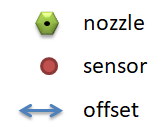
There are four possible positions of the sensor, this results in the following schematics for the sensor area limits (transparent red area):
1. Sensor at the back-right:
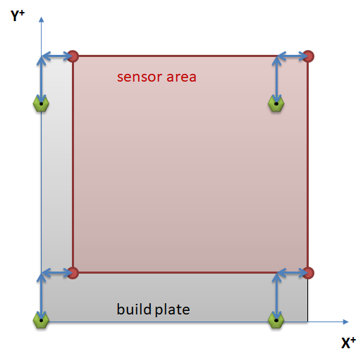
This implies that the sensor can reach the back and the right borders, so the limits are set by:
#define LEFT_PROBE_BED_POSITION (X_PROBE_OFFSET_FROM_EXTRUDER)
#define RIGHT_PROBE_BED_POSITION (X_BED_SIZE)
#define FRONT_PROBE_BED_POSITION (Y_PROBE_OFFSET_FROM_EXTRUDER)
#define BACK_PROBE_BED_POSITION (Y_BED_SIZE)
Note that if a minimum probe offset is defined by #define MIN_PROBE_EDGE [value] in the configuration (to account for sensor width/dimension), the bed limits are changed resulting in (where t = MIN_PROBE_EDGE):
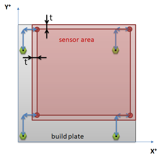
Limits are then set by:
#define LEFT_PROBE_BED_POSITION (X_PROBE_OFFSET_FROM_EXTRUDER + MIN_PROBE_EDGE)
#define RIGHT_PROBE_BED_POSITION (X_BED_SIZE - MIN_PROBE_EDGE)
#define FRONT_PROBE_BED_POSITION (Y_PROBE_OFFSET_FROM_EXTRUDER + MIN_PROBE_EDGE)
#define BACK_PROBE_BED_POSITION (Y_BED_SIZE - MIN_PROBE_EDGE)
In the following sensor position placements, this offset for MIN_PROBE_EDGE will be accounted for.
2. Sensor at the back-left:
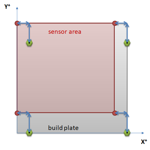
This implies that the sensor can reach the back and the left borders (for zero MIN_PROBE_EDGE), so the limits are set by:
#define LEFT_PROBE_BED_POSITION (MIN_PROBE_EDGE)
#define RIGHT_PROBE_BED_POSITION (X_BED_SIZE  + X_PROBE_OFFSET_FROM_EXTRUDER - MIN_PROBE_EDGE)
#define FRONT_PROBE_BED_POSITION (Y_PROBE_OFFSET_FROM_EXTRUDER + MIN_PROBE_EDGE)
#define BACK_PROBE_BED_POSITION (Y_BED_SIZE - MIN_PROBE_EDGE)
3. Sensor at the front-left:
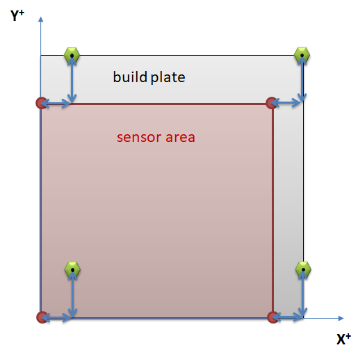
This implies that the sensor can reach the front and the left borders (for zero MIN_PROBE_EDGE), so the limits are set by:
#define LEFT_PROBE_BED_POSITION (MIN_PROBE_EDGE)
#define RIGHT_PROBE_BED_POSITION (X_BED_SIZE  + X_PROBE_OFFSET_FROM_EXTRUDER - MIN_PROBE_EDGE)
#define FRONT_PROBE_BED_POSITION (MIN_PROBE_EDGE)
#define BACK_PROBE_BED_POSITION (Y_BED_SIZE + Y_PROBE_OFFSET_FROM_EXTRUDER - MIN_PROBE_EDGE)
4. Sensor at the front-right:
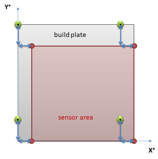
This implies that the sensor can reach the front and the right borders (for zero MIN_PROBE_EDGE), so the limits are set by:
#define LEFT_PROBE_BED_POSITION (X_PROBE_OFFSET_FROM_EXTRUDER + MIN_PROBE_EDGE)
#define RIGHT_PROBE_BED_POSITION (X_BED_SIZE  - MIN_PROBE_EDGE)
#define FRONT_PROBE_BED_POSITION (MIN_PROBE_EDGE)
#define BACK_PROBE_BED_POSITION (Y_BED_SIZE + Y_PROBE_OFFSET_FROM_EXTRUDER - MIN_PROBE_EDGE)
This should have tackled the basics for defining the sensor area limits. It becomes a little more complicated when there is extra travel space. A very easy use of extra travel space can be found in the configuration file; e.g:
// Travel limits (mm) after homing, corresponding to endstop positions.
#define X_MIN_POS [XX]
#define Y_MIN_POS [YY]
where [XX] and [YY] are offset values from endstop to origin (orange arrows represent X_MIN_POS and Y_MIN_POS):
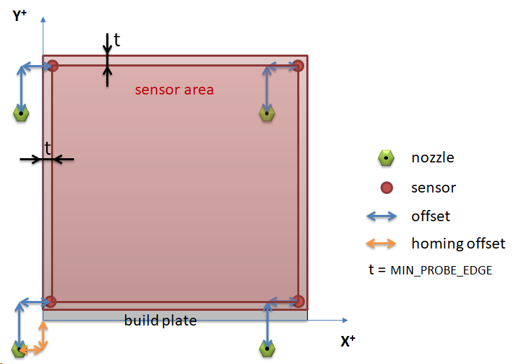 Results in offset constants for a back-right probe:
#define LEFT_PROBE_BED_POSITION (X_PROBE_OFFSET_FROM_EXTRUDER + X_MIN_POS + MIN_PROBE_EDGE)
#define RIGHT_PROBE_BED_POSITION (X_BED_SIZE - MIN_PROBE_EDGE)
#define FRONT_PROBE_BED_POSITION (Y_PROBE_OFFSET_FROM_EXTRUDER + Y_MIN_POS + MIN_PROBE_EDGE)
#define BACK_PROBE_BED_POSITION (Y_BED_SIZE - MIN_PROBE_EDGE)
For all other options, a similar addition of the homing offsets can applied.
A similar addition is possible if the print head is able to travel further on the X or Y axis at the other ends of the axes.
Thoughts for solution for Marlin 2.0.x
As I mentioned earlier, Marlin 2.0.x uses bed edge offsets rather than absolute positions. In analogy of the previous graphs we can draw a bed limits diagram (the example below assumes a back-right mounted probe!):
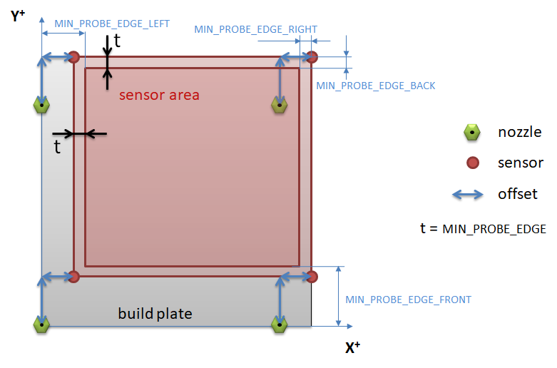
Note that the offsets from the edge need to be defined, to properly do this we need access to the definition of the nozzle offset:
#define NOZZLE_TO_PROBE_OFFSET { XXX, YYY, ZZZ }
As this is the part that defines the array values, you first need to make an array (note that this is a simple solution that many people should be able to understand with limited programming skills, more elegant solutions use the XYZ struct to access the X, Y or Z properties):
Note that Marlin 2.0.x automatically adjusts your probe area based on the defined offset and the MIN_PROBE_EDGE defined for all 4 sides of the bed.
see:
#if PROBE_SELECTED && !IS_KINEMATIC
  #define MIN_PROBE_EDGE_LEFT MIN_PROBE_EDGE
  #define MIN_PROBE_EDGE_RIGHT MIN_PROBE_EDGE
  #define MIN_PROBE_EDGE_FRONT MIN_PROBE_EDGE
  #define MIN_PROBE_EDGE_BACK MIN_PROBE_EDGE
#endif


