Minor fixes (SI units, image descriptions and hover tags), tidied links.
Source Link
Greenonline
  • 6.7k
  • 8
  • 39
  • 68

I was attempting to install new TMC2208 chips on my MKS Gen L v1.0. Everything was going swell, I just had one more thing to do.

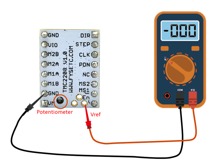
I was checking and tuning the Vref for TMC2208 by measuring voltage across the GND pin and the through-hole shown in this pic (from Stepper drivers - TMC2208):

From https://wiki.fysetc.com/TMC2208/Checking current motor setting

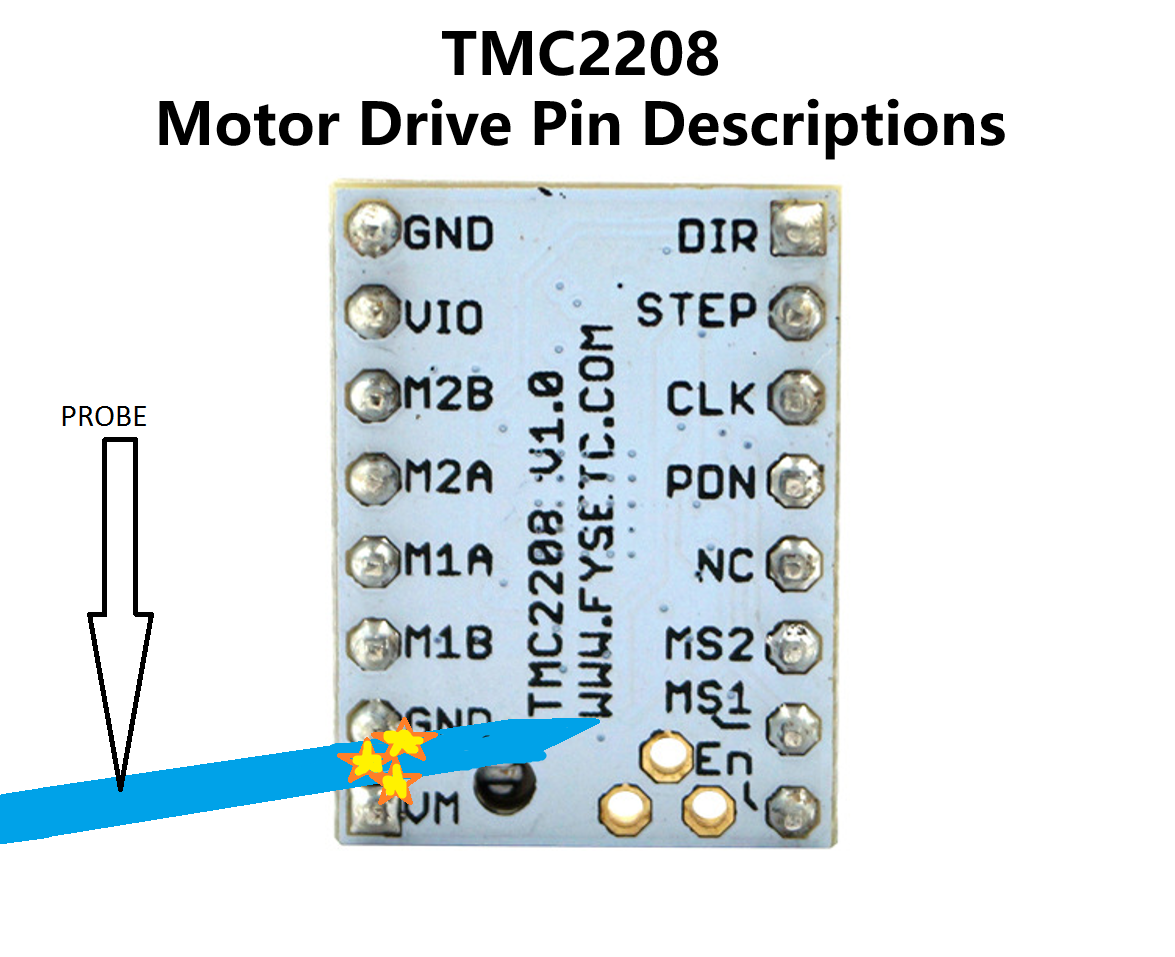
However during very last measurement on the X-axis stepper I slipped and the probe on my meter shorted the GND and VM pins on the TMC2208!! Pic below:

enter image description hereIllustration of shorted pins

Immediately my board turned off, LCD went out, then I unplugged the printer as fast as I could, but the damage was done. My board now does not power on completely when connected only to the PSU.

The LED D7 will flicker on and off, as will the LCD screen. BUTHowever, if I connect the board over USB I am able to connect and interact with the board just fine.

I have meticulously checked the board for blown components but can't see any damage. The two fuses near the 12 V power on the board are not blown.

Is anyone able to offer some insight on this? Does it sound like a salvageable board?

Comment responses:

@Oscar: Thanks and yes I've (attempted) to power the board without anything plugged-in/attached to see if it works, but no dice.

@Tom: There is a lot packed into your comment that required searching for info to even respond. The 5V5 V voltage regulator on my MKS Gen L v1.0 board looks to be an MP1584en chip. Seen in pic below from https://www.monolithicpower.com/pub/media/document/MP1584_r1.0.pdf:

enter image description hereMP1584en pin out

When I connect the board via USB and test the Vin pin, I see a steady ~4.2 volts V . When I remove USB and connect straight to the power supply I see a unsteady Vin between 6-7 volts V .

So I would like to trace from this MP1584EN back to my 12v12 V power source on the board. However, after searching it appears that the schematics for the MKS Gen L v1.0 are not available openly. Unless there is an avenue to find the schematic which I have overlooked. Anyone that can link me to them would be much appreciated.

@R: OP's level is a green-horn baby kitten at its very first rodeo. However your suggestion appeals to me because it sounds like a quick easy soldering fix. To better understand, do you mean to take my 12 volts V from the power source then connect it to different regulator (usb car charger) and then on the secondary side of the car charger, connect it back into my board?

If you're willing to give a bit more of a description this is something I'd definitely be willing to try.

Thanks for all the responses.
I was attempting to install new TMC2208 chips on my MKS Gen L v1.0. Everything was going swell, I just had one more thing to do.

I was checking and tuning the Vref for TMC2208 by measuring voltage across the GND pin and the through-hole shown in this pic:

From https://wiki.fysetc.com/TMC2208/

However during very last measurement on the X-axis stepper I slipped and the probe on my meter shorted the GND and VM pins on the TMC2208!! Pic below:

enter image description here

Immediately my board turned off, LCD went out, then I unplugged the printer as fast as I could, but the damage was done. My board now does not power on completely when connected only to the PSU.

The LED D7 will flicker on and off, as will the LCD screen. BUT if I connect the board over USB I am able to connect and interact with the board just fine.

I have meticulously checked the board for blown components but can't see any damage. The two fuses near the 12 V power on the board are not blown.

Is anyone able to offer some insight on this? Does it sound like a salvageable board?

Comment responses:

@Oscar: Thanks and yes I've (attempted) to power the board without anything plugged-in/attached to see if it works, but no dice.

@Tom: There is a lot packed into your comment that required searching for info to even respond. The 5V voltage regulator on my MKS Gen L v1.0 board looks to be an MP1584en chip. Seen in pic below from https://www.monolithicpower.com/pub/media/document/MP1584_r1.0.pdf:

enter image description here

When I connect the board via USB and test the Vin pin, I see a steady ~4.2 volts. When I remove USB and connect straight to the power supply I see a unsteady Vin between 6-7 volts.

So I would like to trace from this MP1584EN back to my 12v power source on the board. However, after searching it appears that the schematics for the MKS Gen L v1.0 are not available openly. Unless there is an avenue to find the schematic which I have overlooked. Anyone that can link me to them would be much appreciated.

@R: OP's level is a green-horn baby kitten at its very first rodeo. However your suggestion appeals to me because it sounds like a quick easy soldering fix. To better understand, do you mean to take my 12 volts from the power source then connect it to different regulator (usb car charger) and then on the secondary side of the car charger, connect it back into my board?

If you're willing to give a bit more of a description this is something I'd definitely be willing to try.

Thanks for all the responses.
I was attempting to install new TMC2208 chips on my MKS Gen L v1.0. Everything was going swell, I just had one more thing to do.

I was checking and tuning the Vref for TMC2208 by measuring voltage across the GND pin and the through-hole shown in this pic (from Stepper drivers - TMC2208):

Checking current motor setting

However during very last measurement on the X-axis stepper I slipped and the probe on my meter shorted the GND and VM pins on the TMC2208!! Pic below:

Illustration of shorted pins

Immediately my board turned off, LCD went out, then I unplugged the printer as fast as I could, but the damage was done. My board now does not power on completely when connected only to the PSU.

The LED D7 will flicker on and off, as will the LCD screen. However, if I connect the board over USB I am able to connect and interact with the board just fine.

I have meticulously checked the board for blown components but can't see any damage. The two fuses near the 12 V power on the board are not blown.

Is anyone able to offer some insight on this? Does it sound like a salvageable board?

Comment responses:

@Oscar: Thanks and yes I've (attempted) to power the board without anything plugged-in/attached to see if it works, but no dice.

@Tom: There is a lot packed into your comment that required searching for info to even respond. The 5 V voltage regulator on my MKS Gen L v1.0 board looks to be an MP1584en chip. Seen in pic below from MP1584_r1.0.pdf:

MP1584en pin out

When I connect the board via USB and test the Vin pin, I see a steady ~4.2 V . When I remove USB and connect straight to the power supply I see a unsteady Vin between 6-7 V .

So I would like to trace from this MP1584EN back to my 12 V power source on the board. However, after searching it appears that the schematics for the MKS Gen L v1.0 are not available openly. Unless there is an avenue to find the schematic which I have overlooked. Anyone that can link me to them would be much appreciated.

@R: OP's level is a green-horn baby kitten at its very first rodeo. However your suggestion appeals to me because it sounds like a quick easy soldering fix. To better understand, do you mean to take my 12 V from the power source then connect it to different regulator (usb car charger) and then on the secondary side of the car charger, connect it back into my board?

If you're willing to give a bit more of a description this is something I'd definitely be willing to try.

Thanks for all the responses.

deleted 1 character in body
Source Link

I was attempting to install new TMC2208 chips on my MKS Gen L v1.0. Everything was going swell, I just had one more thing to do.

I was checking and tuning the Vref for TMC2208 by measuring voltage across the GND pin and the through-hole shown in this pic:

From https://wiki.fysetc.com/TMC2208/

However during very last measurement on the X-axis stepper I slipped and the probe on my meter shorted the GND and VM pins on the TMC2208!! Pic below:

enter image description here

Immediately my board turned off, LCD went out, then I unplugged the printer as fast as I could, but the damage was done. My board now does not power on completely when connected only to the PSU.

The LED D7 will flicker on and off, as will the LCD screen. BUT if I connect the board over USB I am able to connect and interact with the board just fine.

I have meticulously checked the board for blown components but can't see any damage. The two fuses near the 12 V power on the board are not blown.

Is anyone able to offer some insight on this? Does it sound like a salvageable board?

Comment responses:

@Oscar: Thanks and yes I've (attempted) to power the board without anything plugged-in/attached to see if it works, but no dice.

@Tom: There is a lot packed into your comment that required searching for info to even respond. The 5V voltage regulator on my MKS Gen L v1.0 board looks to be an MP1584en chip. Seen in pic below from https://www.monolithicpower.com/pub/media/document/MP1584_r1.0.pdf:

enter image description here

When I connect the board via USB and test the Vin pin, I see a steady ~4.2 volts. When I remove USB and connect straight to the power supply I see a unsteady Vin between 6-7 volts.

So I would like to trace from this MP1584EN back to my 12v power source on the board. However, after searching it appears that the schematics for the MKS Gen L v1.0 are not available openly. Unless there is an avenue to find the schematic which I have overlooked. Anyone that can link me to them would be much appreciated.

@R: OP's level is a green-horn baby kitten at it'sits very first rodeo. However your suggestion appeals to me because it sounds like a quick easy soldering fix. To better understand, do you mean to take my 12 volts from the power source then connect it to different regulator (usb car charger) and then on the secondary side of the car charger, connect it back into my board?

If you're willing to give a bit more of a description this is something I'd definitely be willing to try.

Thanks for all the responses.

I was attempting to install new TMC2208 chips on my MKS Gen L v1.0. Everything was going swell, I just had one more thing to do.

I was checking and tuning the Vref for TMC2208 by measuring voltage across the GND pin and the through-hole shown in this pic:

From https://wiki.fysetc.com/TMC2208/

However during very last measurement on the X-axis stepper I slipped and the probe on my meter shorted the GND and VM pins on the TMC2208!! Pic below:

enter image description here

Immediately my board turned off, LCD went out, then I unplugged the printer as fast as I could, but the damage was done. My board now does not power on completely when connected only to the PSU.

The LED D7 will flicker on and off, as will the LCD screen. BUT if I connect the board over USB I am able to connect and interact with the board just fine.

I have meticulously checked the board for blown components but can't see any damage. The two fuses near the 12 V power on the board are not blown.

Is anyone able to offer some insight on this? Does it sound like a salvageable board?

Comment responses:

@Oscar: Thanks and yes I've (attempted) to power the board without anything plugged-in/attached to see if it works, but no dice.

@Tom: There is a lot packed into your comment that required searching for info to even respond. The 5V voltage regulator on my MKS Gen L v1.0 board looks to be an MP1584en chip. Seen in pic below from https://www.monolithicpower.com/pub/media/document/MP1584_r1.0.pdf:

enter image description here

When I connect the board via USB and test the Vin pin, I see a steady ~4.2 volts. When I remove USB and connect straight to the power supply I see a unsteady Vin between 6-7 volts.

So I would like to trace from this MP1584EN back to my 12v power source on the board. However, after searching it appears that the schematics for the MKS Gen L v1.0 are not available openly. Unless there is an avenue to find the schematic which I have overlooked. Anyone that can link me to them would be much appreciated.

@R: OP's level is a green-horn baby kitten at it's very first rodeo. However your suggestion appeals to me because it sounds like a quick easy soldering fix. To better understand, do you mean to take my 12 volts from the power source then connect it to different regulator (usb car charger) and then on the secondary side of the car charger, connect it back into my board?

If you're willing to give a bit more of a description this is something I'd definitely be willing to try.

Thanks for all the responses.

I was attempting to install new TMC2208 chips on my MKS Gen L v1.0. Everything was going swell, I just had one more thing to do.

I was checking and tuning the Vref for TMC2208 by measuring voltage across the GND pin and the through-hole shown in this pic:

From https://wiki.fysetc.com/TMC2208/

However during very last measurement on the X-axis stepper I slipped and the probe on my meter shorted the GND and VM pins on the TMC2208!! Pic below:

enter image description here

Immediately my board turned off, LCD went out, then I unplugged the printer as fast as I could, but the damage was done. My board now does not power on completely when connected only to the PSU.

The LED D7 will flicker on and off, as will the LCD screen. BUT if I connect the board over USB I am able to connect and interact with the board just fine.

I have meticulously checked the board for blown components but can't see any damage. The two fuses near the 12 V power on the board are not blown.

Is anyone able to offer some insight on this? Does it sound like a salvageable board?

Comment responses:

@Oscar: Thanks and yes I've (attempted) to power the board without anything plugged-in/attached to see if it works, but no dice.

@Tom: There is a lot packed into your comment that required searching for info to even respond. The 5V voltage regulator on my MKS Gen L v1.0 board looks to be an MP1584en chip. Seen in pic below from https://www.monolithicpower.com/pub/media/document/MP1584_r1.0.pdf:

enter image description here

When I connect the board via USB and test the Vin pin, I see a steady ~4.2 volts. When I remove USB and connect straight to the power supply I see a unsteady Vin between 6-7 volts.

So I would like to trace from this MP1584EN back to my 12v power source on the board. However, after searching it appears that the schematics for the MKS Gen L v1.0 are not available openly. Unless there is an avenue to find the schematic which I have overlooked. Anyone that can link me to them would be much appreciated.

@R: OP's level is a green-horn baby kitten at its very first rodeo. However your suggestion appeals to me because it sounds like a quick easy soldering fix. To better understand, do you mean to take my 12 volts from the power source then connect it to different regulator (usb car charger) and then on the secondary side of the car charger, connect it back into my board?

If you're willing to give a bit more of a description this is something I'd definitely be willing to try.

Thanks for all the responses.

added 3 characters in body
Source Link

I was attempting to install new TMC2208 chips on my MKS Gen L v1.0. Everything was going swell, I just had one more thing to do.

I was checking and tuning the Vref for TMC2208 by measuring voltage across the GND pin and the through-hole shown in this pic:

From https://wiki.fysetc.com/TMC2208/

However during very last measurement on the X-axis stepper I slipped and the probe on my meter shorted the GND and VM pins on the TMC2208!! Pic below:

enter image description here

Immediately my board turned off, LCD went out, then I unplugged the printer as fast as I could, but the damage was done. My board now does not power on completely when connected only to the PSU.

The LED D7 will flicker on and off, as will the LCD screen. BUT if I connect the board over USB I am able to connect and interact with the board just fine.

I have meticulously checked the board for blown components but can't see any damage. The two fuses near the 12 V power on the board are not blown.

Is anyone able to offer some insight on this? Does it sound like a salvageable board?

Comment responses:

@Oscar: Thanks and yes I've (attempted) to power the board without anything plugged-in/attached to see if it works, but no dice.

@Tom: There is a lot packed into your comment that required searching for info to even respond. The 5V voltage regulator on my MKS Gen L v1.0 board looks to be an MP1584en chip. Seen in pic below from https://www.monolithicpower.com/pub/media/document/MP1584_r1.0.pdf:

enter image description here

When I connect the board via USB and test the Vin pin, I see a steady ~4.2 volts. When I remove USB and connect straight to the power supply I see a unsteady Vin between 6-7 volts.

So I would like to trace from this MP1584EN back to my 12v power source on the board. However, after searching it appears that the schematics for the MKS Gen L v1.0 are not available openly. Unless there is an avenue to find the schematic which I have overlooked. Anyone that can link me to them would be much appreciated.

@R: OP's level is a green-horn baby kitten at it's very first rodeo. However your suggestion appeals to me because it sounds like a quick easy soldering fix. To better understand, do you mean to take my 12 volts from the power source then connect toit to different regularregulator (usb car charger) and then on the secondary side of the car charger, connect it back into my board?

If you're willing to give a bit more of a description this is something I'd definitely be willing to try.

Thanks for all the responses.

I was attempting to install new TMC2208 chips on my MKS Gen L v1.0. Everything was going swell, I just had one more thing to do.

I was checking and tuning the Vref for TMC2208 by measuring voltage across the GND pin and the through-hole shown in this pic:

From https://wiki.fysetc.com/TMC2208/

However during very last measurement on the X-axis stepper I slipped and the probe on my meter shorted the GND and VM pins on the TMC2208!! Pic below:

enter image description here

Immediately my board turned off, LCD went out, then I unplugged the printer as fast as I could, but the damage was done. My board now does not power on completely when connected only to the PSU.

The LED D7 will flicker on and off, as will the LCD screen. BUT if I connect the board over USB I am able to connect and interact with the board just fine.

I have meticulously checked the board for blown components but can't see any damage. The two fuses near the 12 V power on the board are not blown.

Is anyone able to offer some insight on this? Does it sound like a salvageable board?

Comment responses:

@Oscar: Thanks and yes I've (attempted) to power the board without anything plugged-in/attached to see if it works, but no dice.

@Tom: There is a lot packed into your comment that required searching for info to even respond. The 5V voltage regulator on my MKS Gen L v1.0 board looks to be an MP1584en chip. Seen in pic below from https://www.monolithicpower.com/pub/media/document/MP1584_r1.0.pdf:

enter image description here

When I connect the board via USB and test the Vin pin, I see a steady ~4.2 volts. When I remove USB and connect straight to the power supply I see a unsteady Vin between 6-7 volts.

So I would like to trace from this MP1584EN back to my 12v power source on the board. However, after searching it appears that the schematics for the MKS Gen L v1.0 are not available openly. Unless there is an avenue to find the schematic which I have overlooked. Anyone that can link me to them would be much appreciated.

@R: OP's level is a green-horn baby kitten at it's very first rodeo. However your suggestion appeals to me because it sounds like a quick easy soldering fix. To better understand do you mean to take my 12 volts from the power source then connect to to different regular (usb car charger) and then on the secondary side of the car charger, connect it back into my board?

If you're willing to give a bit more of a description this is something I'd definitely be willing to try.

Thanks for all the responses.

I was attempting to install new TMC2208 chips on my MKS Gen L v1.0. Everything was going swell, I just had one more thing to do.

I was checking and tuning the Vref for TMC2208 by measuring voltage across the GND pin and the through-hole shown in this pic:

From https://wiki.fysetc.com/TMC2208/

However during very last measurement on the X-axis stepper I slipped and the probe on my meter shorted the GND and VM pins on the TMC2208!! Pic below:

enter image description here

Immediately my board turned off, LCD went out, then I unplugged the printer as fast as I could, but the damage was done. My board now does not power on completely when connected only to the PSU.

The LED D7 will flicker on and off, as will the LCD screen. BUT if I connect the board over USB I am able to connect and interact with the board just fine.

I have meticulously checked the board for blown components but can't see any damage. The two fuses near the 12 V power on the board are not blown.

Is anyone able to offer some insight on this? Does it sound like a salvageable board?

Comment responses:

@Oscar: Thanks and yes I've (attempted) to power the board without anything plugged-in/attached to see if it works, but no dice.

@Tom: There is a lot packed into your comment that required searching for info to even respond. The 5V voltage regulator on my MKS Gen L v1.0 board looks to be an MP1584en chip. Seen in pic below from https://www.monolithicpower.com/pub/media/document/MP1584_r1.0.pdf:

enter image description here

When I connect the board via USB and test the Vin pin, I see a steady ~4.2 volts. When I remove USB and connect straight to the power supply I see a unsteady Vin between 6-7 volts.

So I would like to trace from this MP1584EN back to my 12v power source on the board. However, after searching it appears that the schematics for the MKS Gen L v1.0 are not available openly. Unless there is an avenue to find the schematic which I have overlooked. Anyone that can link me to them would be much appreciated.

@R: OP's level is a green-horn baby kitten at it's very first rodeo. However your suggestion appeals to me because it sounds like a quick easy soldering fix. To better understand, do you mean to take my 12 volts from the power source then connect it to different regulator (usb car charger) and then on the secondary side of the car charger, connect it back into my board?

If you're willing to give a bit more of a description this is something I'd definitely be willing to try.

Thanks for all the responses.

added responses to the responses
Source Link
Loading
Improved formatting
Source Link
0scar
  • 37.1k
  • 12
  • 67
  • 155
Loading
Source Link
Loading