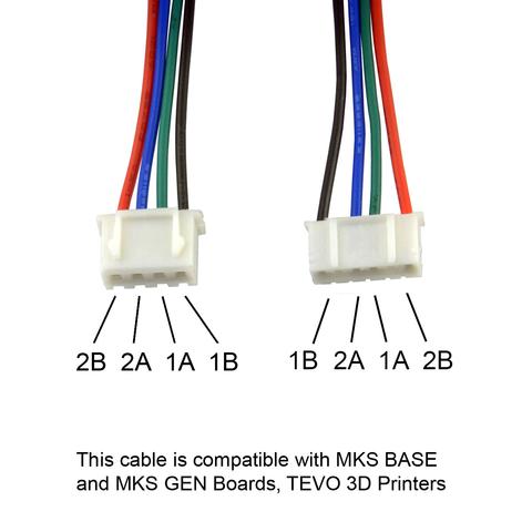
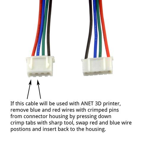
In an attempt to salvage my (sadly) previously incorrect answer, and to add to anttix's superlative answer, here is a quote from Stepper cable for MKS Boards pinout, which clearly shows the difference - locking and non-locking, and pitch difference (note the thickness of the plastic between each individual pin socket) - in the two plugs:
This pinout information will help you to use our 1 meter stepper cables correctly. Cable was made to be compatible with 6-pin JST connectors on NEMA 17 stepper on one side and 4-pin JST connector on other side. These cables are compatible with MKS BASE and MKS Gen boards that we sell in our store.
For compatibility with Anet board you will need to swap 2 wires - RED and BLUE on the 4 pin board side connector.
Whilst they aren't labeled PH and XH, it is pretty safe to assume that:
- For the control board, the 4 pin female connector on the left is the XH, and;
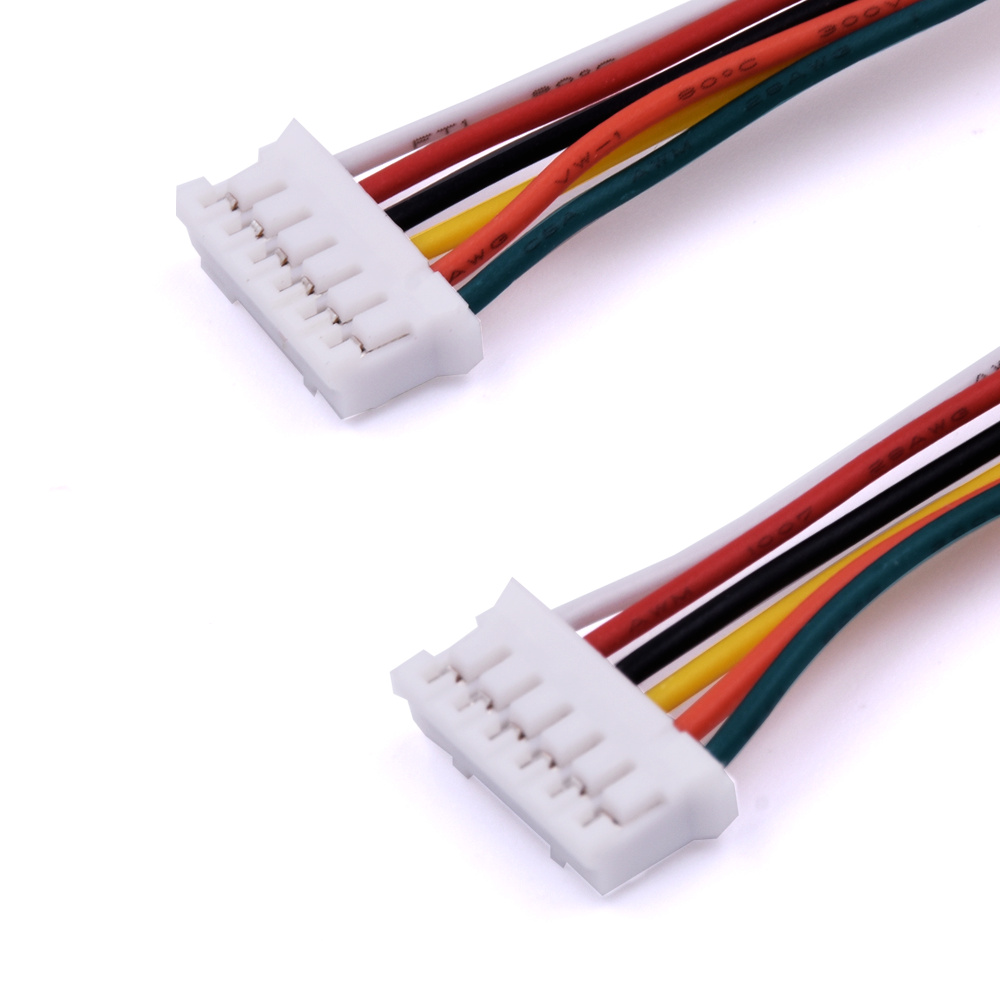
- For the stepper motor, the 6 pin female connector on the right is PH.
The mattmillan.com link in anttix's answer, whilst informative, unfortunately doesn't show both sides of the 4 or 6 pin connector.
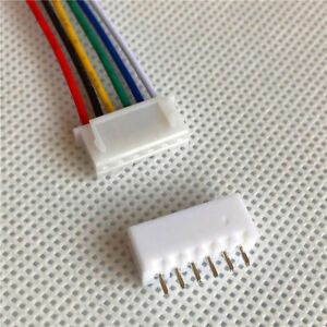
Maybe It is most likely not... JST XH 2.54 6 pin female
and the reverse side, showing the locking, with the male PCB connector


