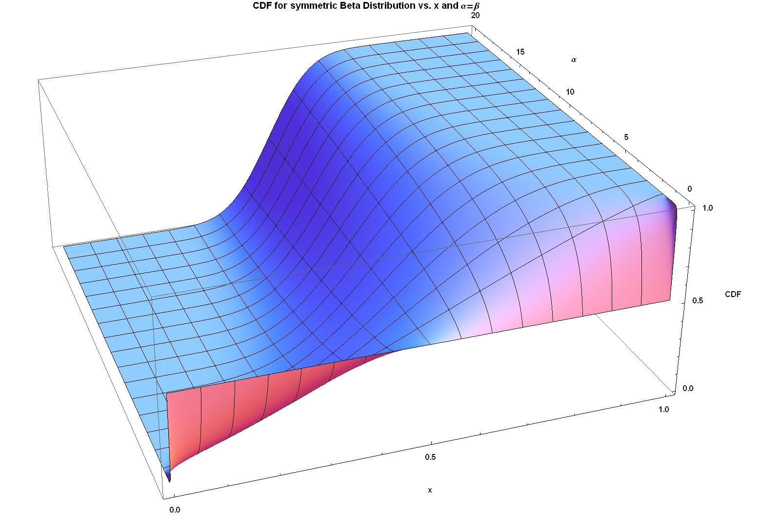
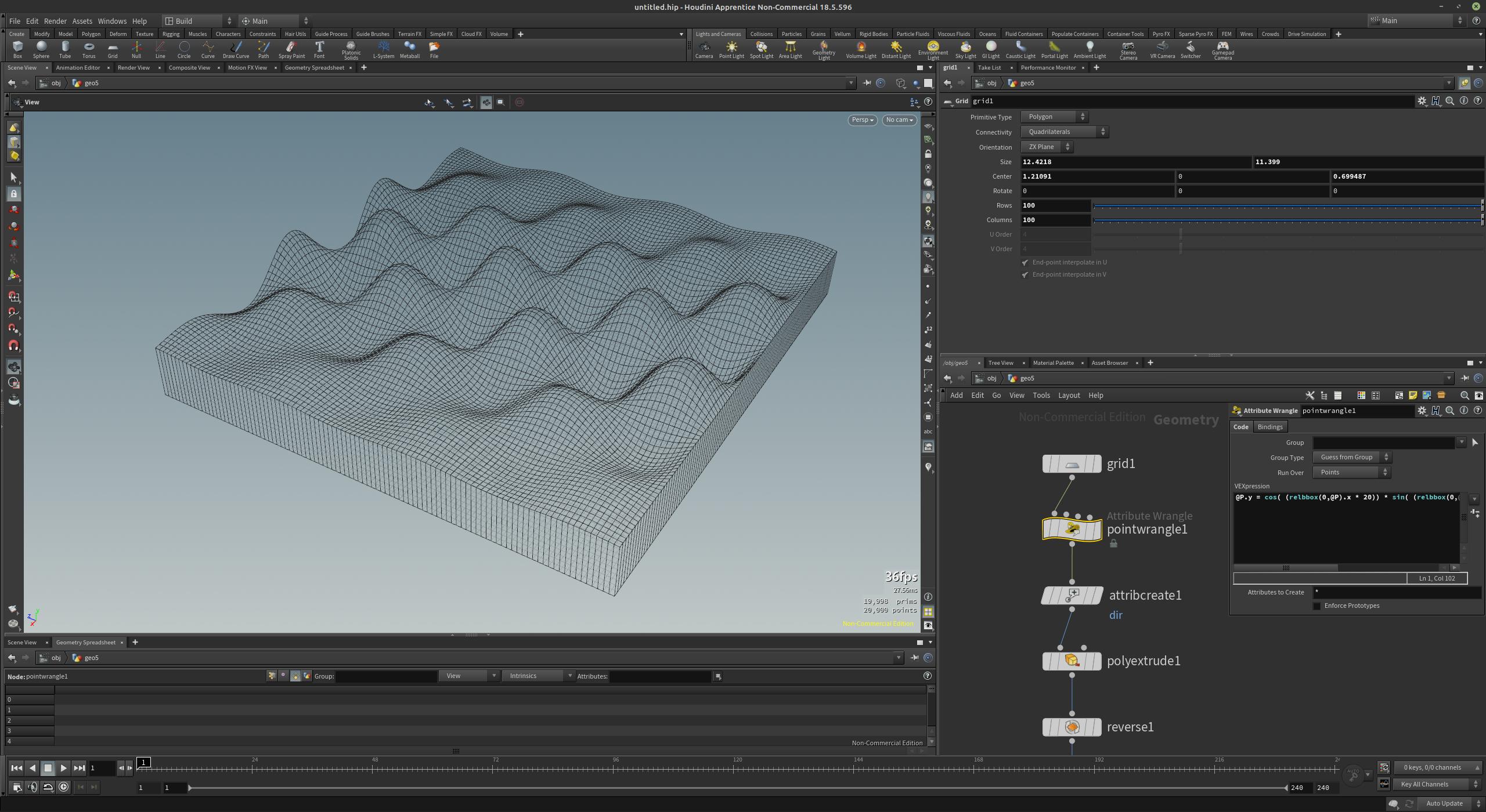
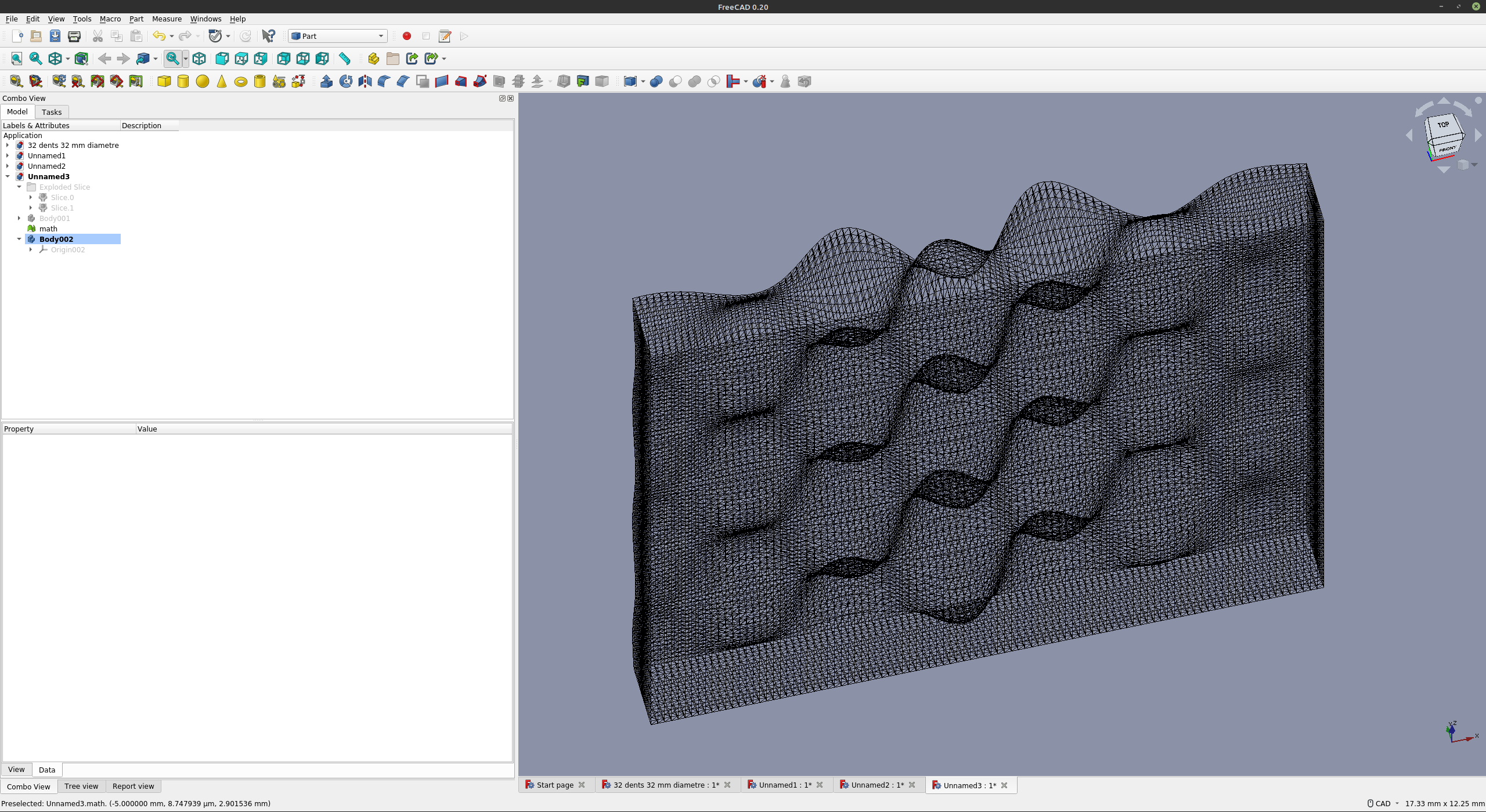
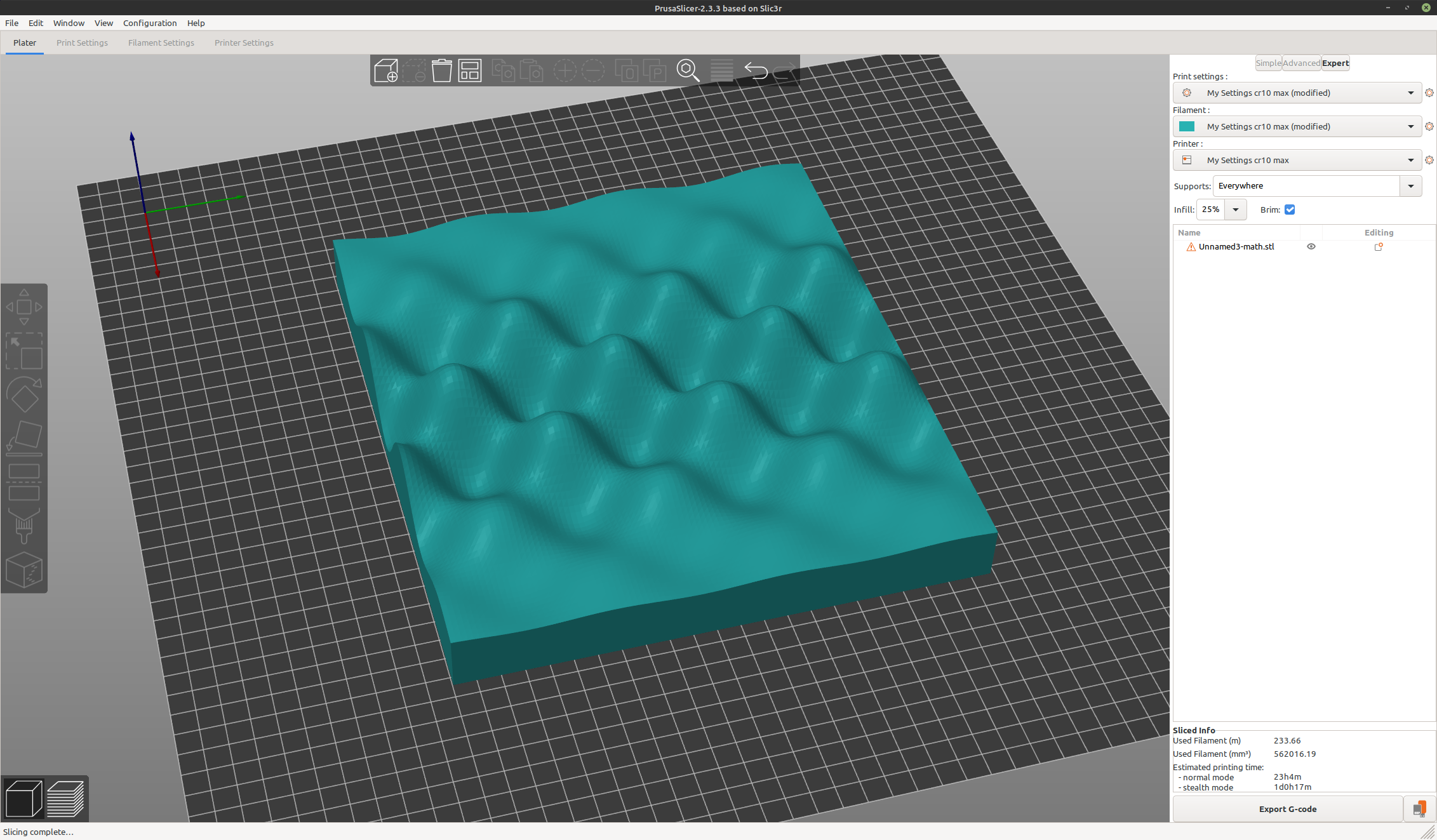
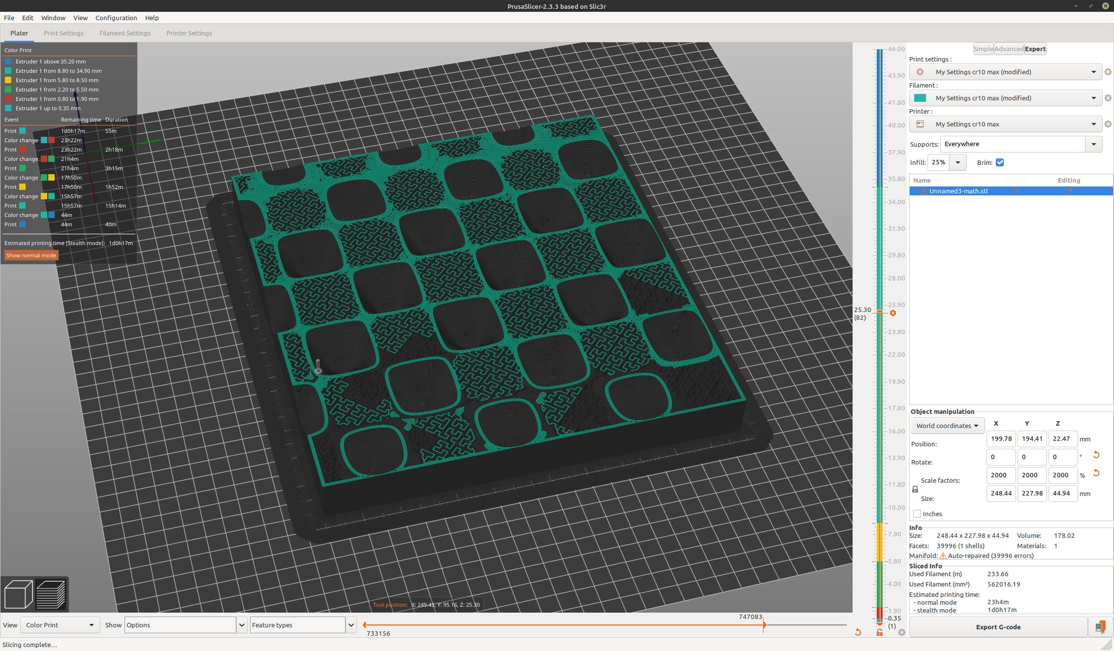
Suppose I have the X, Y, and Z coordinates (either in a list or a function z = f(x,y)) that defines a shape as the one provided and I want to 3D print it with a solid bottom, is there an easy way to do this? If not, how can a functionally well-defined shape be put into a 3D modeling software like FreeCAD?
4 Answers
For stuff like this, OpenSCAD is your friend. There are several different approaches you could take:
Generate an image file with grayscale color representing the height of the function on an XY grid, and use the
surfacefeature to import it as a heightmap.Write the function as a mathematical expression in OpenSCAD language, and write a module to generate a
polyhedronby iterating over a sufficiently fine coordiante grid, sampling the function, and producing points and triangles.Use a library someone else has already written for this purpose. I'm not aware of specific ones but pretty sure there are quite a few.
-
1$\begingroup$ I try to use OpenSCAD when designing and it was my first thought when seeing the question. I have insufficient brain cells to contribute in the manner you did, however. $\endgroup$ Commented Oct 4, 2021 at 17:55
Another option is to use Full Control Designer where you can define the path using Excel formulas and it will generate the GCode for you.
You may generate a .stl file from your mathematical definition. You may write a program using a language of your choice to compute the .stl file.
Your image shows a lot of rectangles, each rectangle may be described as two triangles. The .stl file is a (very long) list of all that triangles. Each triangle is defined by the X, Y, and Z coordinates of the three corners.
solid name

facet normal ni nj nk
    outer loop
        vertex v1x v1y v1z
        vertex v2x v2y v2z
        vertex v3x v3y v3z
    endloop
endfacet

endsolid name
Each n or v is a floating-point number in sign-mantissa-"e"-sign-exponent format, e.g., "2.648000e-002". The triangle vertices should be sorted using the "right-hand rule", i.e. the vertices are listed in counter-clockwise order from outside.
The normal vector ni nj nk is set to zero.
The G-code file is generated from the .stl file using the slicing software for your 3D printer.
See https://en.wikipedia.org/wiki/STL_(file_format) for details.
Not sure what you're asking exactly, but you can use this workflow:
