3
$\begingroup$

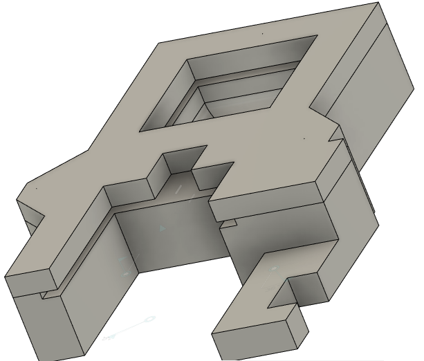
When designing for 3d FDM printing, I'm wondering what is best practice for items with large overhangs which cannot have (or would be fairly impractical) support structures. Consider my following design:

enter image description here

This item is about 7" long, and you'll notice the narrow slot running through the middle of it. The slot is 0.100" wide.

I was about to print this when I suddenly realized printing it would be a problem. So I started messing around with painting on supports, but since something slides in this slot, I would have to do some extensive cleanup to make sure it's smooth.

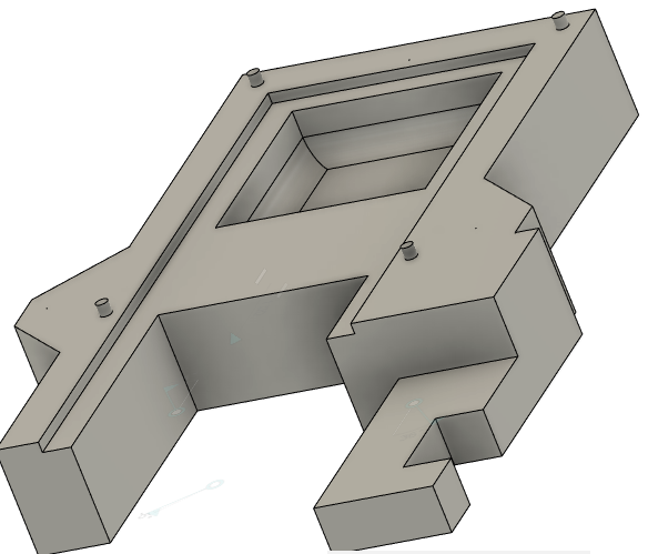
What I ended up doing was splitting the body at the start of the overhang, and placing some alignment pins in the body (with corresponding holes in the upper portion of the body. e.g.

enter image description here

I will print the top and bottom separately and glue them together.

My question is whether this is my only option or if I'm missing something in the design process which might work better? This design is in Fusion360, in case that matters when discussing some specific tools that are available which I'm unaware of.
$\endgroup$
1
  • $\begingroup$ Note also that FDM™ is registered to a specific company. The generic equivalent is FFF. $\endgroup$
    – fred_dot_u
    Commented Nov 21, 2022 at 1:43

3 Answers 3

5
$\begingroup$

When constructing a model intended to be 3D printed, your approach is sound. Overhangs and the required supports can be a severe problem and I believe your assessment is accurate.

The complexity of the upper portion would make printed supports an inappropriate path for the reasons you've provided, while your solution eliminates all the negative aspects of this model's construction/design.

The split as presented turns an excessively supported print into two completely unsupported, easily-printed sections. The alignment pins are the perfect approach as well.

You've not indicated an aversion to adhesive, another plus in the overall assessment. Printing the model(s) in the orientation displayed is going to provide the most strength from the plastic. In some models, one can change the orientation to eliminate or reduce supports, but too often the layer direction change results in a weaker object. Your split design removes that factor as well.

$\endgroup$
3
  • $\begingroup$ Thank you for the feedback. Is there a preferred adhesive for this? I'm using PLA. I was able to print successfully and glue these two together with CA glue, medium viscosity, using accelerant. There isn't any (shouldn't be!) any stress across the joint, but am interested if there's a better solution for other projects. $\endgroup$
    – LarryBud
    Commented Nov 21, 2022 at 15:16
  • 3
    $\begingroup$ My experience with CA products is that they become brittle and fail over time. If the part is not experiencing any flexure, it may be sufficient. A "goo" type adhesive may be preferable if there is flexure. One such product is E6000, also ShoeGoo. It's fairly viscous (gooey!) and bonds well after 24 hours. $\endgroup$
    – fred_dot_u
    Commented Nov 21, 2022 at 15:30
  • $\begingroup$ @fred_dot_u I personally prefer epoxy type adhesives, as I experienced that most "universal glues" are horribly inadequate to do any gluing. $\endgroup$
    – Trish
    Commented Nov 27, 2022 at 15:18
2
$\begingroup$

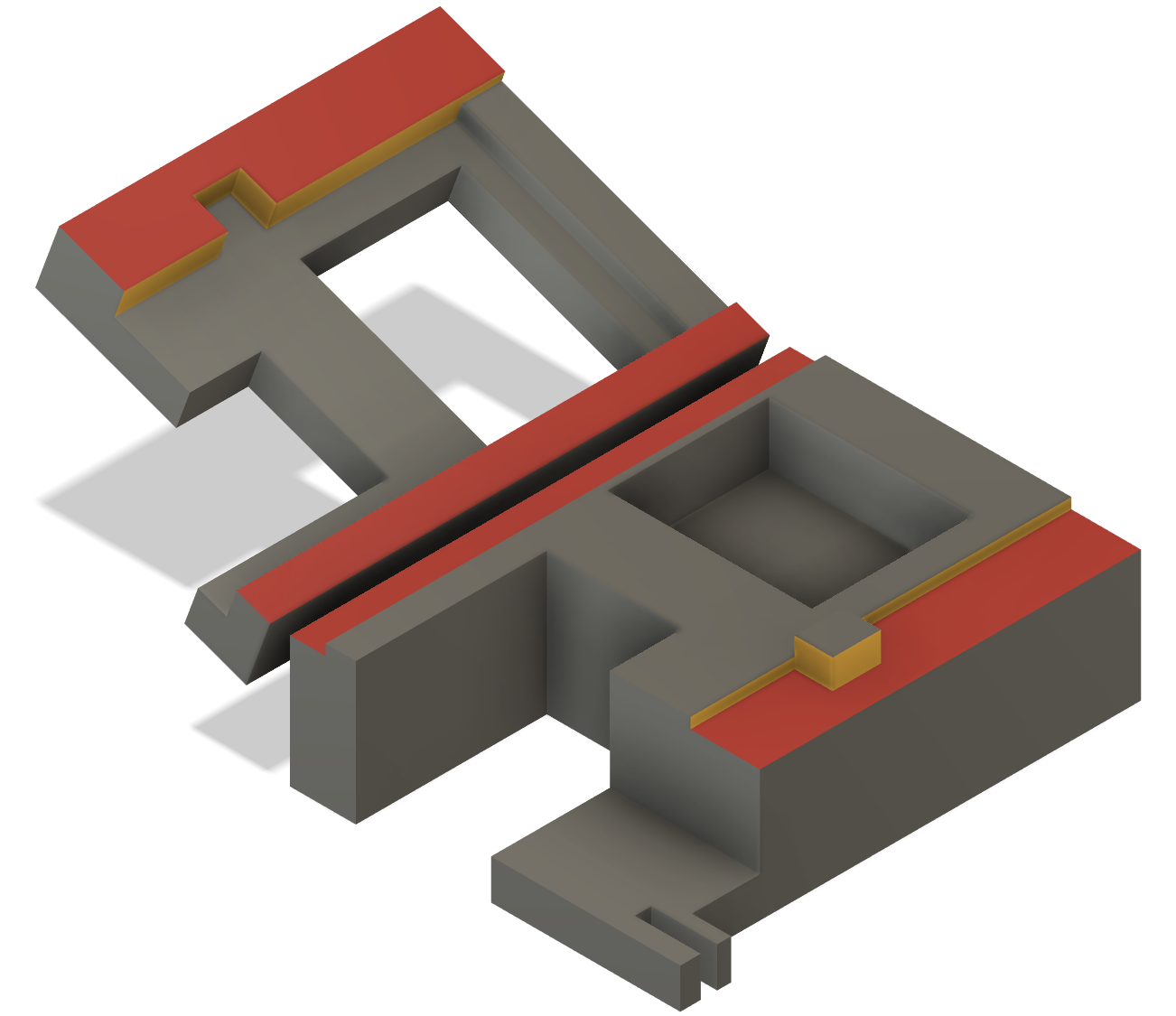
While slicing into slabs and the use of alignment pins is a perfectly viable solution, including the alignment features organically into a single print can make assembly faster. In this case, the model itself acts as an alignment feature or might even act as the clamp, at the cost of creating a more complex cut. An additional benefit of a more complex cut is the elimination of separate alignment pins and getting the glue surfaces away from parts that need a critical dimension

As an example, I used an approximation of your model and shifted the cut layer around some (more complex) to get a natural left-right alignment feature from the deep cut, and then added a high "peak" on the model to act as a front-back alignment feature. The yellow faces ensure alignment in this case, and the red faces are main glue faces.

enter image description here

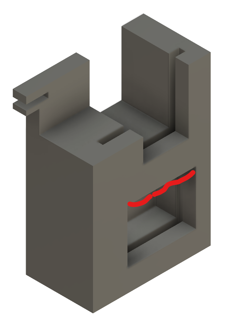
Also, keep in mind point orientation can alter things a lot: printing on the "back" as we both modeled, the slot needs support. However, there is an orientation that remove the need to support the slot's top and instead only requires support in the pocket, possibly eliminating the need for a two-part print at the cost of needing to remove the support in the area marked red, but which, as a pocket without undercuts, should be decently easy:

enter image description here

$\endgroup$
2
  • 2
    $\begingroup$ Pretty cool solution and will keep that in mind in the design process. I found adding the pins after the fact just a 60 second mod to the design. As far as printing vertically, I contemplated that, but wanted the 'door" which slides in the slot to run parallel to the print layers to reduce friction as much as possible. It also would add time and filament to the print. Might have been a little to cautious on my end, however. $\endgroup$
    – LarryBud
    Commented Nov 27, 2022 at 13:30
  • 1
    $\begingroup$ @LarryBud that's a valid consideration, smoothness of the slot and post processing time. The main point was to remember that it is something you should think about. See also 3dprinting.stackexchange.com/questions/6726/… $\endgroup$
    – Trish
    Commented Nov 27, 2022 at 13:32
0
$\begingroup$

If your end product allows it, one possible solution would be to remodel your part so that instead of having a square channel in the center, the channel had sloping or curved sides so that the overhand was removed, and then to print out an infill piece that could be clotted into the channel to square it off.

In essence, you would turn the square channel into a triangular notch with shallow sides that didn't need supporting, and then you restore it to being square after it's printed.

This would also have the advantage of meaning that you could print the infill to a much higher standard than the rest of the print, so it was stronger.

$\endgroup$

You must log in to answer this question.

Not the answer you're looking for? Browse other questions tagged .