5
$\begingroup$

So I'm finally building a new firmware (Repetier) since my current one can't be edited. It is a Delta printer and is explained in detail here: Help with Repetier firmware (probably locked and licensed)

There are many variables that I couldn't find in the EEPROM. Can someone please explain those to me (listed below)? I've listed only the ones I feel are the most important for now.

General and Dimensions:

  1. KILL_METHOD

  2. STARTUP_GCODE

  3. DELTA_FLOOR_SAFETY_MARGIN_MM

  4. Max. horizontal radius (DELTA_MAX_RADIUS): I have "max printable radius" and "delta radius" A(0), B(0) & C(0) each.

  5. Radius error column A/B/C (DELTA_RADIUS_CORRECTION_A/B/C): Could this be the delta radii A(0), B(0) & C(0)?


Z-correction (distortion correction)

  1. Full correction until (FC) or DISTORTION_START_DEGRADE

  2. Reduce correction to zero at (RZ) or DISTORTION_END_HEIGHT

  3. Correction radius (DISTORTION_CORRECTION_R)

  4. Update every x computations (DISTORTION_UPDATE_FREQUENCY)

I have the following in EEPROM:

  1. Z-probe height [mm]
  2. Max. z-probe - bed dist. [mm]
  3. Z-probe speed [mm/s]
  4. Z-probe x-y-speed [mm/s]
  5. Z-probe offset x [mm]
  6. Z-probe offset y [mm]
  7. Z-probe X1 [mm]
  8. Z-probe Y1 [mm]
  9. Z-probe X2 [mm]
  10. Z-probe Y2 [mm]
  11. Z-probe X3 [mm]
  12. Z-probe Y3 [mm]
  13. Z-probe bending correction A [mm]
  14. Z-probe bending correction B [mm]
  15. Z-probe bending correction C [mm]

Stepper

  1. ENABLE_BACKLASH_COMPENSATION
  2. ALLOW_QUADSTEPPING

Endstops

  1. ENDSTOP_PULLUP_X_MIN/ENDSTOP_X_MIN_INVERTING
  2. ENDSTOP_PULLUP_Y_MIN/ENDSTOP_Y_MIN_INVERTING
  3. ENDSTOP_PULLUP_Z_MIN/ENDSTOP_Z_MIN_INVERTING
  4. ENDSTOP_PULLUP_X_MAX/ENDSTOP_X_MAX_INVERTING
  5. ENDSTOP_PULLUP_Y_MAX/ENDSTOP_Y_MAX_INVERTING
  6. ENDSTOP_PULLUP_Z_MAX/ENDSTOP_Z_MAX_INVERTING

Fused Filament Fabrication

  1. EXTRUDER_SWITCH_XY_SPEED

Also, how do I find out which temperature sensors are being used for the extruders? Where are they located?

Here's the EEPROM data:

<Repetier-Firmware-EEPROM>
<epr pos="1028" type="0" value="0">Language</epr>
<epr pos="75" type="2" value="115200">Baudrate</epr>
<epr pos="129" type="3" value="32.752">Filament printed [m]</epr>
<epr pos="125" type="2" value="21644">Printer active [s]</epr>
<epr pos="79" type="2" value="0">Max. inactive time [ms,0=off]</epr>
<epr pos="83" type="2" value="360000">Stop stepper after inactivity [ms,0=off]</epr>
<epr pos="11" type="3" value="80.0000">Steps per mm</epr>
<epr pos="23" type="3" value="200.000">Max. feedrate [mm/s]</epr>
<epr pos="35" type="3" value="20.000">Homing feedrate [mm/s]</epr>
<epr pos="39" type="3" value="10.000">Max. jerk [mm/s]</epr>
<epr pos="133" type="3" value="-140.000">X min pos [mm]</epr>
<epr pos="137" type="3" value="-140.000">Y min pos [mm]</epr>
<epr pos="141" type="3" value="0.000">Z min pos [mm]</epr>
<epr pos="145" type="3" value="140.000">X max length [mm]</epr>
<epr pos="149" type="3" value="140.000">Y max length [mm]</epr>
<epr pos="153" type="3" value="313.280">Z max length [mm]</epr>
<epr pos="59" type="3" value="2000.000">Acceleration [mm/s^2]</epr>
<epr pos="71" type="3" value="2000.000">Travel acceleration [mm/s^2]</epr>
<epr pos="881" type="3" value="355.200">Diagonal rod length [mm]</epr>
<epr pos="885" type="3" value="186.990">Horizontal rod radius at 0,0 [mm]</epr>
<epr pos="925" type="3" value="140.000">Max printable radius [mm]</epr>
<epr pos="891" type="1" value="70">Segments/s for travel</epr>
<epr pos="889" type="1" value="180">Segments/s for printing</epr>
<epr pos="893" type="1" value="0">Tower X endstop offset [steps]</epr>
<epr pos="895" type="1" value="0">Tower Y endstop offset [steps]</epr>
<epr pos="897" type="1" value="0">Tower Z endstop offset [steps]</epr>
<epr pos="901" type="3" value="210.000">Alpha A(210):</epr>
<epr pos="905" type="3" value="330.000">Alpha B(330):</epr>
<epr pos="909" type="3" value="90.000">Alpha C(90):</epr>
<epr pos="913" type="3" value="0.000">Delta Radius A(0):</epr>
<epr pos="917" type="3" value="0.000">Delta Radius B(0):</epr>
<epr pos="921" type="3" value="0.000">Delta Radius C(0):</epr>
<epr pos="933" type="3" value="0.000">Corr. diagonal A [mm]</epr>
<epr pos="937" type="3" value="0.000">Corr. diagonal B [mm]</epr>
<epr pos="941" type="3" value="0.000">Corr. diagonal C [mm]</epr>
<epr pos="1024" type="3" value="1.000">Coating thickness [mm]</epr>
<epr pos="808" type="3" value="0.800">Z-probe height [mm]</epr>
<epr pos="929" type="3" value="10.000">Max. z-probe - bed dist. [mm]</epr>
<epr pos="812" type="3" value="5.000">Z-probe speed [mm/s]</epr>
<epr pos="840" type="3" value="70.000">Z-probe x-y-speed [mm/s]</epr>
<epr pos="800" type="3" value="0.000">Z-probe offset x [mm]</epr>
<epr pos="804" type="3" value="0.000">Z-probe offset y [mm]</epr>
<epr pos="816" type="3" value="-95.260">Z-probe X1 [mm]</epr>
<epr pos="820" type="3" value="-55.000">Z-probe Y1 [mm]</epr>
<epr pos="824" type="3" value="95.260">Z-probe X2 [mm]</epr>
<epr pos="828" type="3" value="-55.000">Z-probe Y2 [mm]</epr>
<epr pos="832" type="3" value="0.000">Z-probe X3 [mm]</epr>
<epr pos="836" type="3" value="110.000">Z-probe Y3 [mm]</epr>
<epr pos="1036" type="3" value="0.000">Z-probe bending correction A [mm]</epr>
<epr pos="1040" type="3" value="0.000">Z-probe bending correction B [mm]</epr>
<epr pos="1044" type="3" value="0.000">Z-probe bending correction C [mm]</epr>
<epr pos="880" type="0" value="1">Autolevel active (1/0)</epr>
<epr pos="106" type="0" value="1">Bed Heat Manager [0-3]</epr>
<epr pos="107" type="0" value="255">Bed PID drive max</epr>
<epr pos="124" type="0" value="80">Bed PID drive min</epr>
<epr pos="108" type="3" value="196.000">Bed PID P-gain</epr>
<epr pos="112" type="3" value="33.000">Bed PID I-gain</epr>
<epr pos="116" type="3" value="290.000">Bed PID D-gain</epr>
<epr pos="120" type="0" value="255">Bed PID max value [0-255]</epr>
<epr pos="1020" type="0" value="0">Enable retraction conversion [0/1]</epr>
<epr pos="992" type="3" value="3.000">Retraction length [mm]</epr>
<epr pos="996" type="3" value="13.000">Retraction length extruder switch [mm]</epr>
<epr pos="1000" type="3" value="40.000">Retraction speed [mm/s]</epr>
<epr pos="1004" type="3" value="0.000">Retraction z-lift [mm]</epr>
<epr pos="1008" type="3" value="0.000">Extra extrusion on undo retract [mm]</epr>
<epr pos="1012" type="3" value="0.000">Extra extrusion on undo switch retract [mm]</epr>
<epr pos="1016" type="3" value="20.000">Retraction undo speed</epr>
<epr pos="200" type="3" value="93.000">Extr.1 steps per mm</epr>
<epr pos="204" type="3" value="150.000">Extr.1 max. feedrate [mm/s]</epr>
<epr pos="208" type="3" value="20.000">Extr.1 start feedrate [mm/s]</epr>
<epr pos="212" type="3" value="5000.000">Extr.1 acceleration [mm/s^2]</epr>
<epr pos="216" type="0" value="3">Extr.1 heat manager [0-3]</epr>
<epr pos="217" type="0" value="230">Extr.1 PID drive max</epr>
<epr pos="245" type="0" value="40">Extr.1 PID drive min</epr>
<epr pos="218" type="3" value="7.0000">Extr.1 PID P-gain/dead-time</epr>
<epr pos="222" type="3" value="2.0000">Extr.1 PID I-gain</epr>
<epr pos="226" type="3" value="40.0000">Extr.1 PID D-gain</epr>
<epr pos="230" type="0" value="255">Extr.1 PID max value [0-255]</epr>
<epr pos="231" type="2" value="0">Extr.1 X-offset [steps]</epr>
<epr pos="235" type="2" value="0">Extr.1 Y-offset [steps]</epr>
<epr pos="290" type="2" value="0">Extr.1 Z-offset [steps]</epr>
<epr pos="239" type="1" value="1">Extr.1 temp. stabilize time [s]</epr>
<epr pos="250" type="1" value="150">Extr.1 temp. for retraction when heating [C]</epr>
<epr pos="252" type="1" value="0">Extr.1 distance to retract when heating [mm]</epr>
<epr pos="254" type="0" value="255">Extr.1 extruder cooler speed [0-255]</epr>
<epr pos="300" type="3" value="93.000">Extr.2 steps per mm</epr>
<epr pos="304" type="3" value="150.000">Extr.2 max. feedrate [mm/s]</epr>
<epr pos="308" type="3" value="20.000">Extr.2 start feedrate [mm/s]</epr>
<epr pos="312" type="3" value="5000.000">Extr.2 acceleration [mm/s^2]</epr>
<epr pos="316" type="0" value="3">Extr.2 heat manager [0-3]</epr>
<epr pos="317" type="0" value="230">Extr.2 PID drive max</epr>
<epr pos="345" type="0" value="40">Extr.2 PID drive min</epr>
<epr pos="318" type="3" value="7.0000">Extr.2 PID P-gain/dead-time</epr>
<epr pos="322" type="3" value="2.0000">Extr.2 PID I-gain</epr>
<epr pos="326" type="3" value="40.0000">Extr.2 PID D-gain</epr>
<epr pos="330" type="0" value="255">Extr.2 PID max value [0-255]</epr>
<epr pos="331" type="2" value="0">Extr.2 X-offset [steps]</epr>
<epr pos="335" type="2" value="0">Extr.2 Y-offset [steps]</epr>
<epr pos="390" type="2" value="0">Extr.2 Z-offset [steps]</epr>
<epr pos="339" type="1" value="1">Extr.2 temp. stabilize time [s]</epr>
<epr pos="350" type="1" value="150">Extr.2 temp. for retraction when heating [C]</epr>
<epr pos="352" type="1" value="0">Extr.2 distance to retract when heating [mm]</epr>
<epr pos="354" type="0" value="255">Extr.2 extruder cooler speed [0-255]</epr>

Sorry for the long, detailed and potentially frustrating question. I'm really new to this.

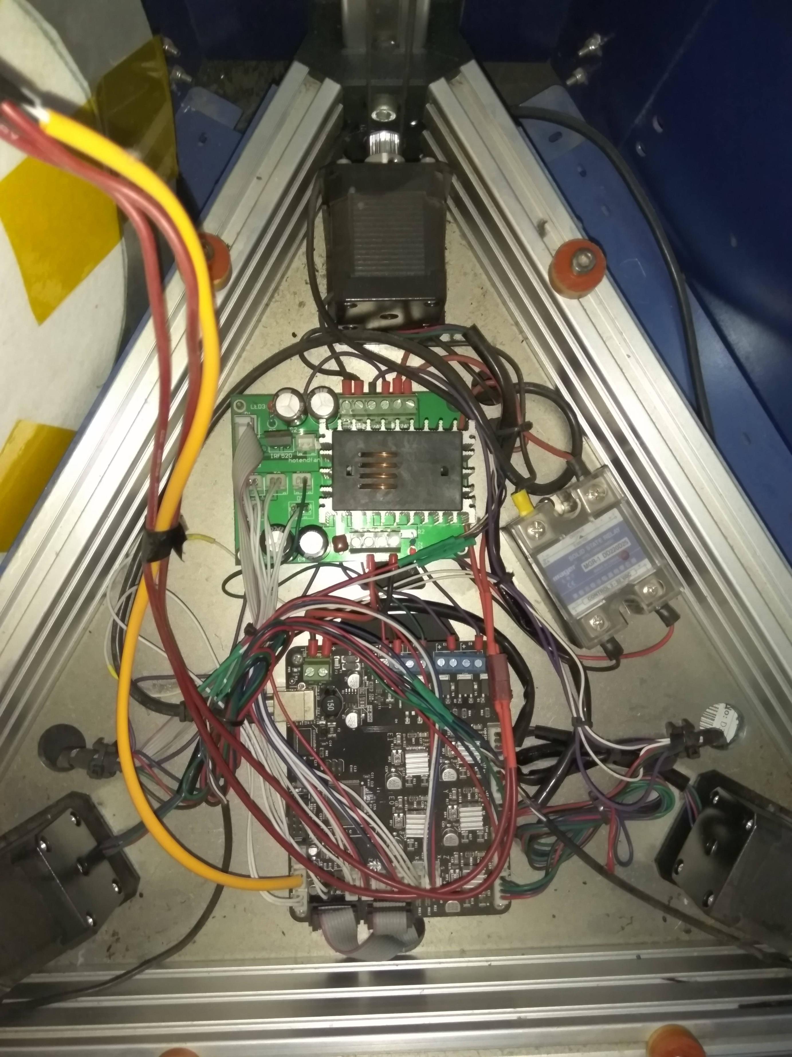
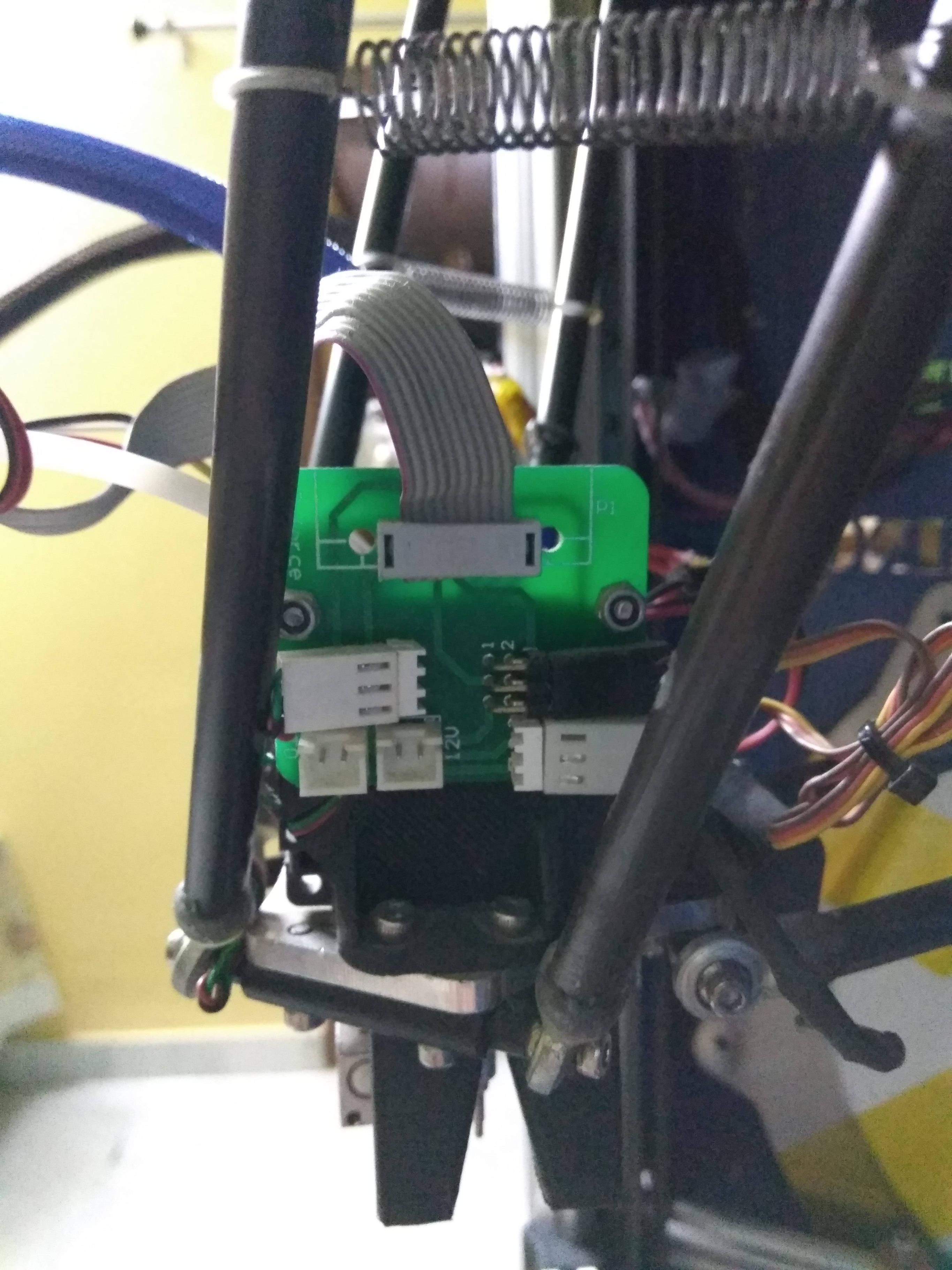
Edit: To be more comprehensive, I'm including pictures of the controller boards.

Main controller board

Hot-end PCB

Also, I've traced the printer down to a Taiwanese manufacturer: http://d-force.tw/

There are a few parts available: Hot-end PCB, Main controller board & Servo motor for calibration (Z-probe). I haven't been able to find the other board (with the HRD12008 SMPS on it and placed just beside the main controller board), yet.

Does this change things? If yes then how?

I'm going ahead with burning a new firmware on the current board only because changing the board and shield combo seems too complicated to me. Is it though?
$\endgroup$
4
  • $\begingroup$ It might be worth just restating the make and model of your printer, in this question, to save people having to click the link to your previous question :-) $\endgroup$
    – Greenonline
    Commented Jun 4, 2017 at 0:46
  • $\begingroup$ @Greenonline please have a look at the firmware downloaded from repetier website. Its asking for pins used for z-probe etc while compiling. The link is: drive.google.com/drive/folders/… $\endgroup$ Commented Jun 9, 2017 at 8:52
  • 1
    $\begingroup$ @Greenonline thank you so much :) The printer does have a z-probe. I've edited my question. Please let me know how it changes things. $\endgroup$ Commented Jun 9, 2017 at 18:57
  • $\begingroup$ @Greenonline sure. I too agree that these questions have been branching out a lot. As soon as I get enough clarity regarding firmware variables, calibration and controller boards I will consolidate all info contained in the comments of those respective questions. I've asked a new question here: 3dprinting.stackexchange.com/questions/4213/… $\endgroup$ Commented Jun 10, 2017 at 8:55

1 Answer 1

2
$\begingroup$

Each of the settings have informative comments written just before the setting's #define, so reading those can point you in the right direction - if the required value doesn't jump out at you from your EEPROM settings.

Taking an educated guess (and I could be wrong), and after looking at the comments, I would imagine that:


General and Dimensions:

  1. KILL_METHOD. From Repetier firmware configuration questions (prusa mendel)

    I would select the second kill method since it allows to continue with your printer after a crash.

    So, you want to have

    #define KILL_METHOD 1
    
  2. No idea, at the moment

  3. You can either measure the height the carriage is from the floor, when the rod(s) is(are) horizontal, or just use the default 15 to be safe - it is probably best to double check this and physically measure it, to prevent any damage:

    // Margin (mm) to avoid above tower minimum (xMin xMinsteps)
    // If your printer can put its carriage low enough the rod is horizontal without hitting the floor
    // set this to zero. Otherwise, measure how high the carriage is from horizontal rod
    // Also, movement speeds are 10x to 20x cartesian speeds at tower bottom.
    // You may need to leave a few mm for safety.
    // Hitting floor at high speed can damage your printer (motors, drives, etc)
    // THIS MAY NEED UPDATING IF THE HOT END HEIGHT CHANGES!
    #define DELTA_FLOOR_SAFETY_MARGIN_MM 15
    
    1. DELTA_MAX_RADIUS use Max printable radius [mm].
    2. The values you have for Alpha A(210), Alpha B(330) & Alpha C(90) each, would be for:

      #define DELTA_ALPHA_A 210
      #define DELTA_ALPHA_B 330
      #define DELTA_ALPHA_C 90
      
    1. The correction radii should be 0 and are the values you have for Delta Radius A(0), Delta Radius B(0) & Delta Radius C(0):

      /** Correct radius by this value for each column. 
          Perfect builds have 0 everywhere. */
      #define DELTA_RADIUS_CORRECTION_A 0
      #define DELTA_RADIUS_CORRECTION_B 0
      #define DELTA_RADIUS_CORRECTION_C 0
      
    2. Likewise, given your EEPROM settings that you have listed the values you have for Corr. diagonal A[mm], Corr. diagonal B[mm] & Corr. diagonal C[mm]:

      /** Correction of the default diagonal size. Value gets added.*/
      #define DELTA_DIAGONAL_CORRECTION_A 0
      #define DELTA_DIAGONAL_CORRECTION_B 0
      #define DELTA_DIAGONAL_CORRECTION_C 0
      

Z-correction (distortion correction)

  1. DISTORTION_START_DEGRADE - Initially, I would leave this at default. You can always tweak it at a later stage.

    /** z distortion degrades to 0 from this height on. You should start after the first layer to get
    best bonding with surface. */
    #define DISTORTION_START_DEGRADE 0.5
    
  2. DISTORTION_END_HEIGHT - Initially, I would leave this at default. You can always tweak it at a later stage.

    /** z distortion correction gets down to 0 at this height. */
    #define DISTORTION_END_HEIGHT 1.5
    
  3. DISTORTION_CORRECTION_R - Initially, I would leave this at default. You can always tweak it at a later stage.

    /* For delta printers you simply define the measured radius around origin */
    #define DISTORTION_CORRECTION_R       80
    
  4. DISTORTION_UPDATE_FREQUENCY - For the moment, I would leave this at default. As the comments remark, this is computationally intensive, and will use a lot of processing power - power that you want to keep for controlling the motors. SO, it is best to not make this frequency too high.

    /** Correction computation is not a cheap operation and changes are only small. So it
    is not necessary to update it for every sub-line computed. For example lets take DELTA_SEGMENTS_PER_SECOND_PRINT = 150
    and fastest print speed 100 mm/s. So we have a maximum segment length of 100/150 = 0.66 mm.
    Now lats say our point field is 200 x 200 mm with 9 x 9 points. So between 2 points we have
    200 / (9-1) = 25 mm. So we need at least 25 / 0.66 = 37 lines to move to the next measuring
    point. So updating correction every 15 calls gives us at least 2 updates between the
    measured points.
    NOTE: Explicit z changes will always trigger an update!
    */
    #define DISTORTION_UPDATE_FREQUENCY   15
    

Stepper

  1. ENABLE_BACKLASH_COMPENSATION - As stated, it is rarely needed, so leave it set to 0

    /* If you have a backlash in both z-directions, you can use this. For most printer, the bed will be pushed down by it's
    own weight, so this is nearly never needed. */
    #define ENABLE_BACKLASH_COMPENSATION 0
    
  2. ALLOW_QUADSTEPPING - Do you need high frequencies? This could be a case of leaving set to the default of 1, and if you experience stalling then set to 0 to see if it cures the stalling

    /** If you need frequencies off more then 30000 you definitely need to enable this. If you have only 1/8 stepping
    enabling this may cause to stall your moves when 20000Hz is reached.
    */
    #define ALLOW_QUADSTEPPING 1
    

Endstops

  1. ENDSTOP_PULLUP_X_MIN/ENDSTOP_X_MIN_INVERTING - these are relatively easy. From the comment for ENDSTOP_X_MIN_INVERTING

    /* By default all endstops are pulled up to HIGH. You need a pull-up if you
    use a mechanical endstop connected with GND. Set value to false for no pull-up
    on this endstop.
    */
    

    A pullup refers to a pull-up resistor. This is, in this case, a piece of circuitry in the MicroController Unit (MCU) (i.e. the Arduino chip[ATmega 2560] on the controller board. This #define allows you to enable, or disable, it for each input connected to an endstop. Basically, they stop short circuits between the power supply and ground - they do more than that but... You probably need the MAX endstops enabled, where you actually have an endstop. If there are no MIN endstops, i.e. at the bottom of the rails, then these can be set to false.

    #define ENDSTOP_PULLUP_X_MIN false
    #define ENDSTOP_PULLUP_Y_MIN false
    #define ENDSTOP_PULLUP_Z_MIN false
    #define ENDSTOP_PULLUP_X_MAX true
    #define ENDSTOP_PULLUP_Y_MAX true
    #define ENDSTOP_PULLUP_Z_MAX true
    

    ENDSTOP_X_MIN_INVERTING this merely allows you to invert the input from the endstop. For example, if the endstop is triggered by a vertical carriage, then the switch will "close". If, instead, the code is actually looking for an "open" switch, rather than a "closed" switch, when the endstop switch is being triggered by the vertical carriage hitting it, then you simply need to invert it.

    //set to true to invert the logic of the endstops
    #define ENDSTOP_X_MIN_INVERTING true
    #define ENDSTOP_Y_MIN_INVERTING true
    #define ENDSTOP_Z_MIN_INVERTING true
    #define ENDSTOP_X_MAX_INVERTING false
    #define ENDSTOP_Y_MAX_INVERTING false
    #define ENDSTOP_Z_MAX_INVERTING false
    

Fused Filament Fabrication

  1. EXTRUDER_SWITCH_XY_SPEED - Probably best to leave as default, 100, and tweak later, if need be

    /* Speed in mm/s for extruder moves fom internal commands, e.g. switching extruder. */
    #define EXTRUDER_SWITCH_XY_SPEED 100
    

With respect to the temperature sensor settings on the extruder (read: hotend), from Repetier-Firmware Documentation:

#define EXT0_TEMPSENSOR_TYPE 5 

What temperature sensor are you using in the extruder. The configuration file lists possible values and meanings.

#define EXT0_TEMPSENSOR_PIN 0

This parameter is tricky and often causes wrong configurations. For historical reasons it is named PIN but it IS NOT A PIN NUMBER. It is the position in an array of analog input sources. In this array, the real pin number is stored. In 99.9% 0 is the correct answer here.

#define EXT0_HEATER_PIN HEATER_0_PIN

Which pin enables the heater block. It works with any pin. PWM capability is not required to use PID on an output.

For EXT0_TEMPSENSOR_TYPE, the temperature sensor is "buried' inside the hotend heater block, and as such it is probably not going to be easy, nor desirable, to remove and examine - although it is certainly possible to do so, if you feel up to the job. If could be just a question of trial-and-error. You have eight, or so, to choose from. However, the 100k thermistor is one of the most common types, and so 1 would seem like a good setting to choose, initially:

// What type of sensor is used?
// 0 is no thermistor/temperature control
// 1 is 100k thermistor (Epcos B57560G0107F000 - RepRap-Fab.org and many other)
// 2 is 200k thermistor
// 3 is mendel-parts thermistor (EPCOS G550)
// 4 is 10k thermistor
// 8 is ATC Semitec 104GT-2
// 12 is 100k RS thermistor 198-961
// 13 is PT100 for E3D/Ultimaker
// 14 is 100K NTC 3950
// 5 is userdefined thermistor table 0
// 6 is userdefined thermistor table 1
// 7 is userdefined thermistor table 2
// 50 is userdefined thermistor table 0 for PTC thermistors
// 51 is userdefined thermistor table 0 for PTC thermistors
// 52 is userdefined thermistor table 0 for PTC thermistors
// 60 is AD8494, AD8495, AD8496 or AD8497 (5mV/degC and 1/4 the price of AD595 but only MSOT_08 package)
// 61 is AD8494, AD8495, AD8496 or AD8497 (5mV/degC and 1.25 Vref offset like adafruit breakout)
// 97 Generic thermistor table 1
// 98 Generic thermistor table 2
// 99 Generic thermistor table 3
// 100 is AD595
// 101 is MAX6675
// 102 is MAX31855
#define EXT0_TEMPSENSOR_TYPE 1

As the Repetier documentation states, in 99.9% of the cases, for EXT0_TEMPSENSOR_PIN a value of 0 will probably work. If it does not, then you may need to change this to some other value.

For EXT0_HEATER_PIN HEATER_0_PIN, just follow the wiring of your printer, and see which pin the heater is connected to.


Where and how to change the settings

You are probably aware of this already, but in case you aren't...

Once you have downloaded Repetier-Firmware-master.zip from Github.com: repetier/Repetier-Firmware, and unzipped it, then you will need to edit the files in Configuration.h in the src/ArduinoAVR/Repetier directory. Note that the ArduinoAVR directory is used for the Arduino Mega 2560 board, and its derivatives.

Open Repetier.ino in the Arduino IDE, and edit Configuration.h in the Arduino IDE. You could also edit Configuration.h in your favourite plain text editor, if need be, but it is probably easier, and simpler to do everything in the Arduino IDE.

Once you have edited the settings that you require, as I described in Help with Repetier firmware (probably locked and licensed), compile and upload the firmware to your board. Then run a print. If something seems to be incorrectly set, stop the print. Then re-tweak your settings ad compile and upload again, and then run another test print. Ad infinitum...

After a few iterations, you should be quite comfortable with this process, and end up with a well calibrated printer.

$\endgroup$

You must log in to answer this question.

Not the answer you're looking for? Browse other questions tagged .