4
$\begingroup$

I'm not really sure where to ask this question as I think it is a design question, but also a printing question. So if there is a better place to post, I'd be happy to harass someone else.
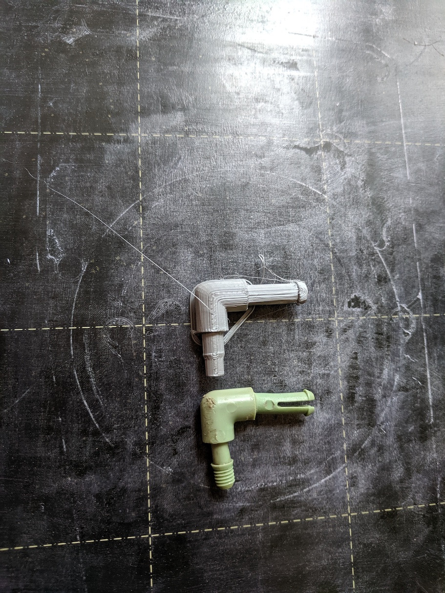
I'm (re)designing a sprinkler manifold for a dripper system because the stupid pegs for this stupid manifold are on top of the manifold, which is a prime spot for any old postal person/dog/raindrop to break off. Of course the pegs aren't sold separately so you have to buy a whole new manifold. Seems like a great use for a 3D printer.

sprinkler pegs

I designed a new manifold and decided the pegs were useful in case they broke off. I was thinking having them screw in would be a better design, but for the life of me I can't get them to actually screw in after I print. Here is the fusion 360 file. This is generally what it looks like: MushroomManifold And here is the resulting stl file.
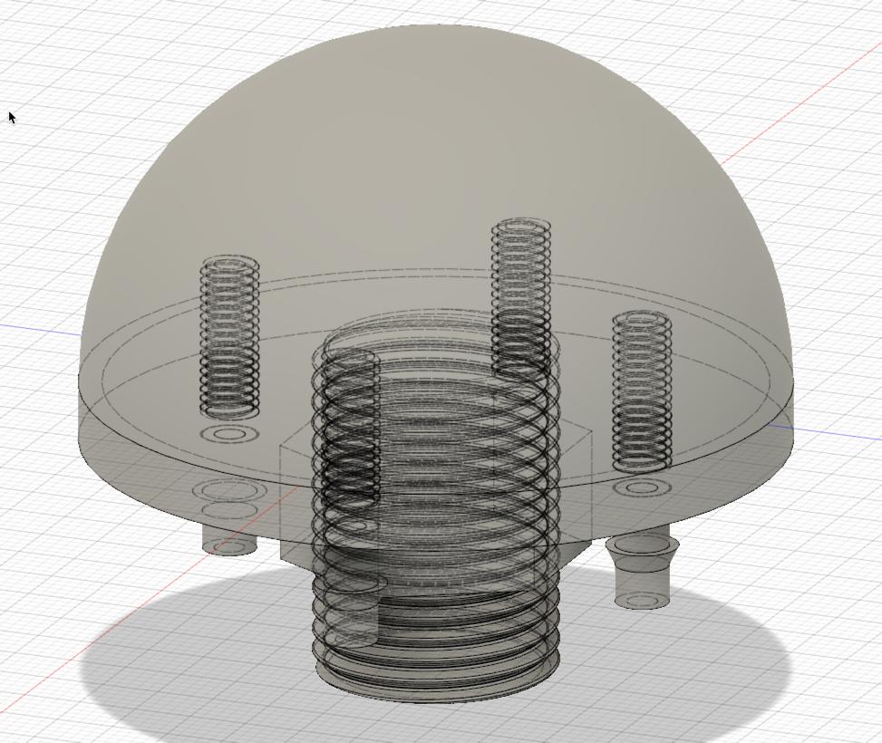
After several prints, the pegs won't screw into the manifold base. I push and I turn and turn but the threads just won't bite. The 3/4" pipe threads fit just fine, so I know threads can be printed, but these pegs are stubborn.

I guess my question is, what's a good design for a peg thingy that needs to attach into a manifold, but also pass water? Should I try to replicate the cantilever thing they have going on, or is a screw better? Any ideas why my pegs won't screw into the base of my mushroom? This is my first attempt at 3d modeling so I'm not totally familiar with all the terminology, so any pointers there would be helpful. Thanks!
$\endgroup$
3
  • 1
    $\begingroup$ It is difficult to make something watertight with 3D printing at high water pressure levels (maybe an epoxy coating on the inside would help out). It could be that the threads are too fine to print, it would be better to make the hole a little smaller and the peg a little bigger in diameter and cut your own threads on both parts. $\endgroup$
    – 0scar
    Commented May 28, 2019 at 6:37
  • 1
    $\begingroup$ I can’t download that file right now, I assume they are some rather small threads. One thing you can do is try making the threads more coarse. Another option is to try printing with the smallest nozzle you can and print even slower. Another is to print the threads aligned vertically with the z axis. Another is to make the threaded part of your piece have a slight conical taper the way pipe threads work. Then you can use the conical shape to get the threads to seal better. You can also use ptfe tape on the threads to help them seal. Also what material are you planning on printing these in? $\endgroup$
    – T. M.
    Commented May 28, 2019 at 10:18
  • $\begingroup$ I've been playing with PLA for the prototypes, but probably ABS for the final product. Open to other suggestions. It will be in the sun probably most of the day and some of them could take a beating. Are sprinklers at "high water" pressures for a .15 or .1 mm layer height? I wasn't thinking they would be too high pressure for that, but I haven't been able to get the pegs in to make a water tight prototype yet. $\endgroup$ Commented May 29, 2019 at 6:01

3 Answers 3

6
$\begingroup$

I examined and sliced your STL file, and the profile of your threads looks very strange.

It's definitely possible to do very strong, perfectly-fitting threads down to small sizes (at least down to M4 or slightly smaller) using modern inexpensive 3D printers, and contrary to widespread belief (there's a well-known YouTube comparison with a major test fallacy claiming otherwise) they should usually be stronger than threaded inserts against being pulled out. But you need to get the thread profile exactly right.

Most real thread profiles are trapezoidal, but yours peak at points and have round bases. This is unlikely to match the external thread on the part you're trying to fit to it, and it's going to have major dimensional accuracy issues because of the sharp point which can't necessarily be represented in the layer resolution.

I'm not familiar with Fusion 360 so I don't know how to tell you exactly, but most CAD software has libraries for generating threads conforming to standard thread profiles. If you want to do 3D printed threads, you should look at those and figure out which one you're trying to match. Or, if you want to replace the pegs with your own design anyway, just pick a reasonable one for both.

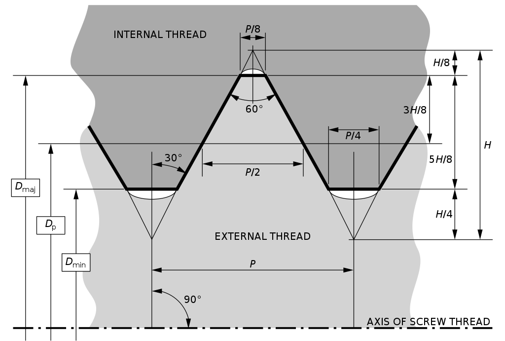
Generally, most modern threads use the basic ISO metric thread profile, even if they're not standard metric diameter or pitch:

ISO Metric Thread Profile diagram

Your cross-sections should look roughly like the "internal thread" side of that.

$\endgroup$
3
  • $\begingroup$ This reminded me that Fusion 360 has a feature to import 3d models from the McMaster-Carr catalog including screw and bolt threads. $\endgroup$
    – T. M.
    Commented May 29, 2019 at 3:00
  • $\begingroup$ Interesting, I hadn't inspected the threads in too much detail. Fusion has a bunch of preset threads that are from some standards. I used ANSI Metric M Profile, but here is a screen shot of the available profiles. I played with a couple, so maybe it is just finding the right one. $\endgroup$ Commented May 29, 2019 at 5:42
  • $\begingroup$ Metric M threads should look like this: en.wikipedia.org/wiki/ISO_metric_screw_thread $\endgroup$ Commented May 29, 2019 at 14:13
1
$\begingroup$

If I may suggest a slight alternative: don't try to make the threads part of the 3Dprint. Instead, thicken the walls where the threads would have been, increasing the ID (inner diameter) of the hole, maybe even "thread" to match the outside of : metal threaded inserts. Those can be screwed in, .
Perhaps a small "T-nut" (pick the size you need) would be sufficient, and you could create holes in your printed part for the penetration tips.

$\endgroup$
4
  • $\begingroup$ Good call, but I think for these simple sprinklers, adding metal inserts might be more than what I need. In this case the pegs are to carry water from the 3/4" pipe to the smaller dripper hoses, so the pegs themselves need to be hollow. $\endgroup$ Commented May 29, 2019 at 5:44
  • $\begingroup$ Or, with tap and die, thread the parts after printing them. $\endgroup$
    – Davo
    Commented May 29, 2019 at 16:24
  • $\begingroup$ @Davo: That should work as long as you ensure that the walls are sufficiently many layers to retain strength after you tap. $\endgroup$ Commented May 29, 2019 at 18:23
  • 1
    $\begingroup$ @R.. Yes, we do this all the time with internal threads. We do four or five perimeters, 35% hexagonal infill. Good for M3 and above in my experience. $\endgroup$
    – Davo
    Commented May 29, 2019 at 19:28
0
$\begingroup$

With the suggestions from @R.., I played with a couple of different screw profiles that come with fusion 360, and found these settings to be helpful:

enter image description here

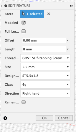
After cutting the hole with these screw settings, I selected all the faces of the hole and off set them by -0.1 mm. Originally, I was offsetting the hole by like -0.02 mm and the peg wouldn't screw. After learning a bit about tolerances of printers, I expanded this to the .1 value and it screwed in magically! I haven't yet worked out if the pegs are water tight, so I may have to revert back to the previous thread settings that seem like they would be tighter, or maybe I'll invest in an o-ring. Suggestions welcome.

Thanks to everyone for their input.

$\endgroup$

You must log in to answer this question.

Not the answer you're looking for? Browse other questions tagged .