1
$\begingroup$

I have read that the cable colours depend on multiple factors:

  • Used voltage
  • Kind of cable
  • Type of voltage (DC or AC)

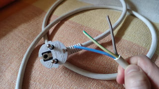
My cable looks like this:

main_cable

I live in Spain, in Europe. The colour codes of the International Electrotechnical Commission for AC circuits are these ones:

enter image description here

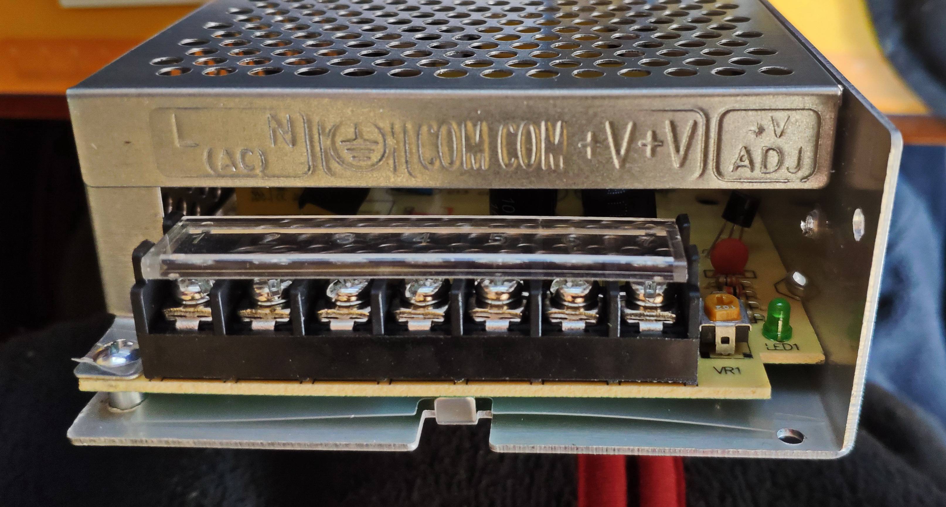
My PSU has these possible connections

front_psu

So I guess these are the connections:

  • L (AC). Brown colour. Single Phase line or Three Phase Line (L1)
  • N (AC). Blue colour. Neutral
  • GND. Green and yellow colours. Protective earth or ground (PE)
  • COM, COM ¿?
  • V, V ¿?
  • V(ADJ). This is a potentiometer, in order to modify the current voltage. Should I touch this?

But I am not sure about what are the COM and the V ports. I assume they are for the DC connections, which is the positive and which the negative? The PSU does not have any manual and I am little lost

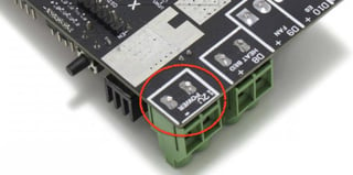
Should I turn the potentiometer to change the voltage to adapt it to the Ramps 1.6 Plus board?

ramps

Please correct me if I made some mistake in my question as well
$\endgroup$

1 Answer 1

2
$\begingroup$

You're quite right :)

  • L (AC): Brown colour. Single Phase line or Three Phase Line (L1)
  • N (AC): Blue colour. Neutral
  • GND: Green and yellow colours. Protective earth or ground (PE)
  • COM: DC Negative (-) - Also referred to as "Common"
  • V+: DC Positive (+)
  • V(ADJ). This is for a potentiometer, in order to modify the output voltage. You won't need this unless your power supply is far off.

The way to go about these things is to connect the AC side and to connect a multimeter to the output terminals (V+ and COM, there are two of them in case you need to wire up more than one connection). I like to lightly tighten down the probes under the terminals, that way you don't have to mess with the connections with the mains terminals exposed.

Now you can plug in the power supply (PSU) and make sure it doesn't start smoking or sparking.

Verify that the PSU is outputting DC 12V (that seems to be the voltage required by your Ramps board according to the picture). After that, you can connect it to the Ramps board (remember to disconnect the PSU before rewiring). If the voltage is anything but around 12 V (+/- 0.5VDC should be safe), you need to verify that the PSU is the correct type for your application.

$\endgroup$
3
  • $\begingroup$ Thank you for devoting your time to my question. Yes, the maximum voltage of my PSU is 12V. So both V+ connectors are connected together? The COM terminals as well? I mean, if I use the first COM, should I use the first V+ for the positive? Does it matter? $\endgroup$
    – ChesuCR
    Commented Apr 1, 2020 at 23:43
  • 2
    $\begingroup$ And very importantly, install fork terminal connectors (and never solder the bare ends). $\endgroup$
    – 0scar
    Commented Apr 2, 2020 at 4:53
  • 1
    $\begingroup$ Yes, internally both COM and both V+ are connected, so just use whatever you feel like, I personally usually select the first of both, so that you know which positive and negative leads go to the same load. It doesn't matter in this application, but in large automation installation stuff like that gets quite important, and it's always good to get into good habits. $\endgroup$
    – Stuggi
    Commented Apr 2, 2020 at 8:17

You must log in to answer this question.

Not the answer you're looking for? Browse other questions tagged .