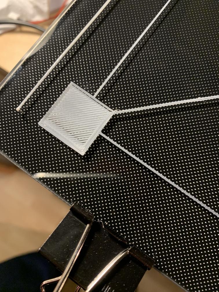
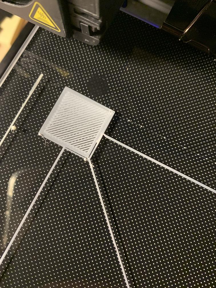
I have an Ender 3 V1 with a glass Creality plate. I was having difficulty using manual levelling and my prints were struggling, so I ordered a 3DTouch. I have installed the 3DTouch and used Creality's BLTouch firmware. But my bed is still not level.
So my build is an Ender 3 V1 with:
- Extruder upgraded to all-metal extruder
- Glass bed upgrade
- 3DTouch Upgrade
- Capricorn Tubing
- Yellow bed springs
I manually levelled my bed using my 3DTouch. I used the G30 command in Pronterface to probe each corner of the plate. At each corner, I would adjust the knob until the 3DTouch read 0.0. I did this iteratively multiple times until I thought it was reasonably level. The four corner values were something like 0.1, 0.0, -0.2, and 0.3 mm.
I have also put a straight edge with an Angle Finder Phone App. The bed is quite level. It reads 0, 1, or 2° depending on how I place the level. X-axis gantry has a 1° tilt.
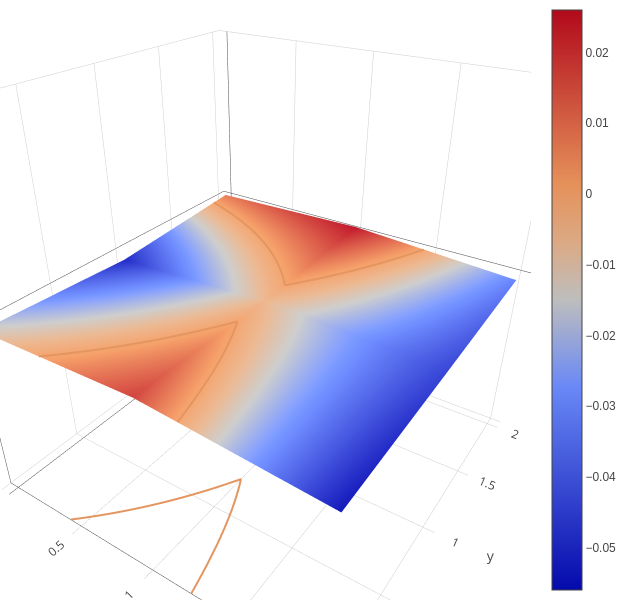
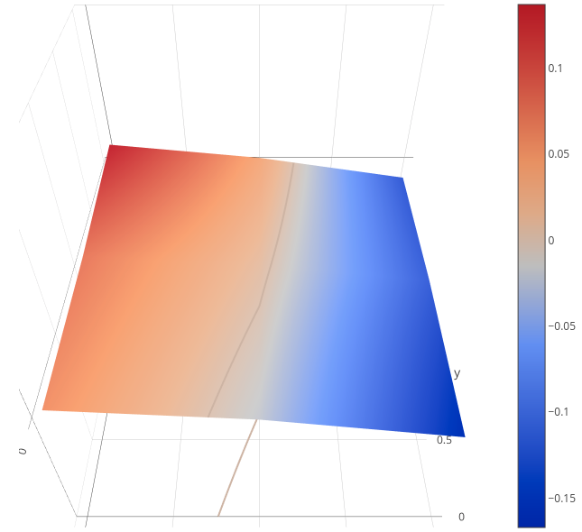
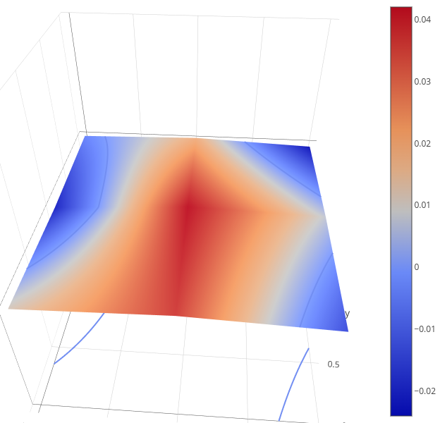
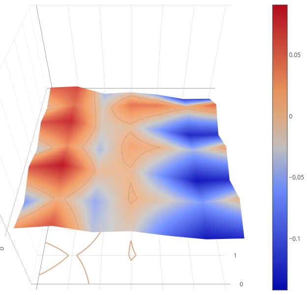
Here is my current bed levelling mesh:
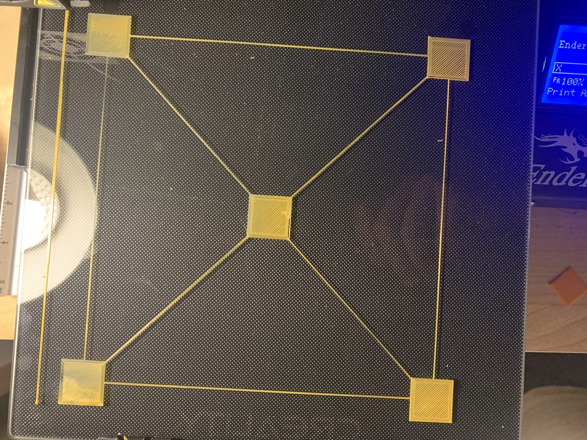
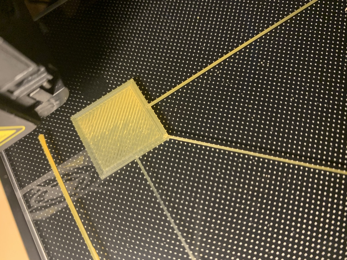
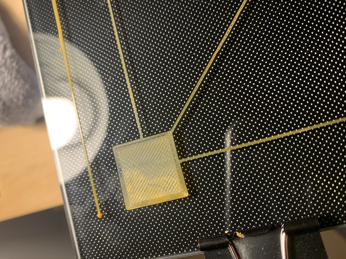
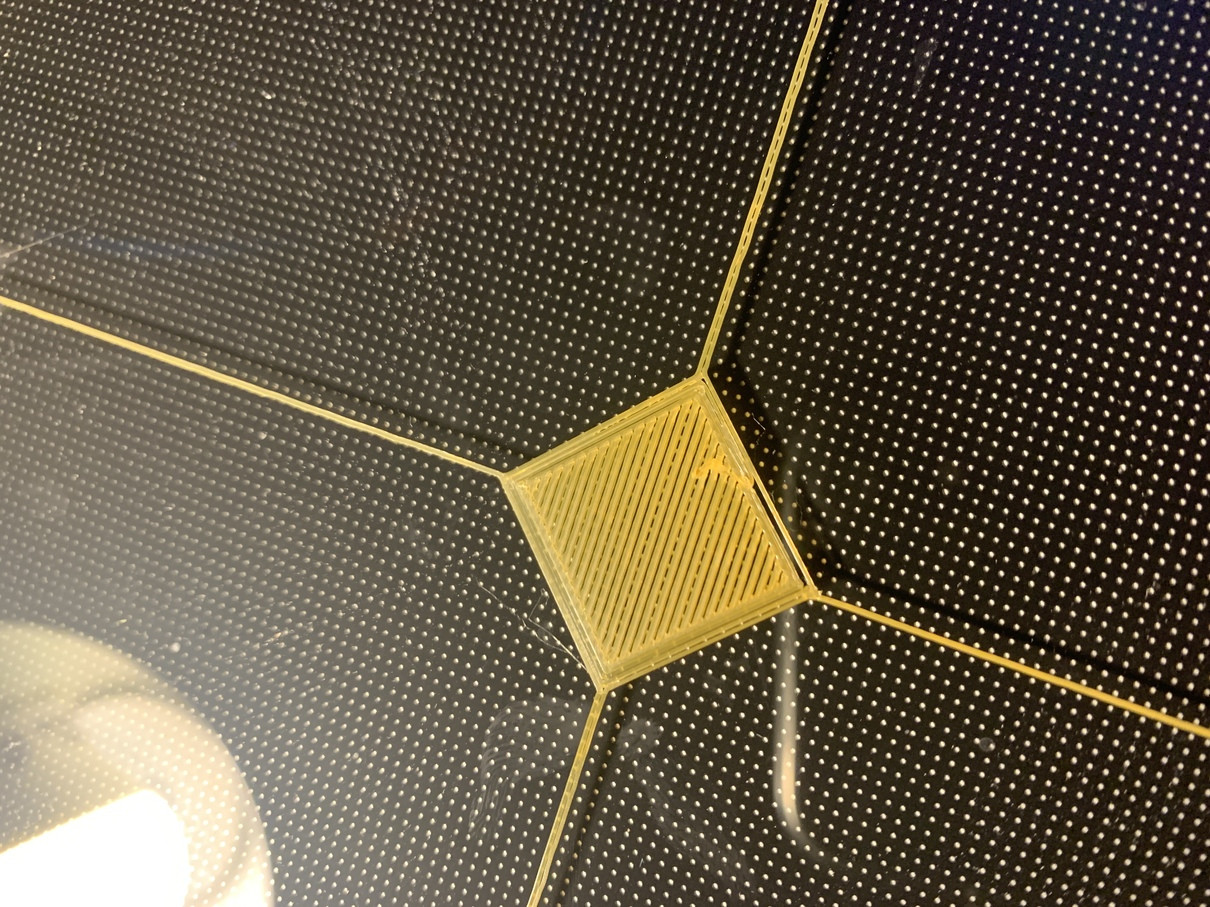
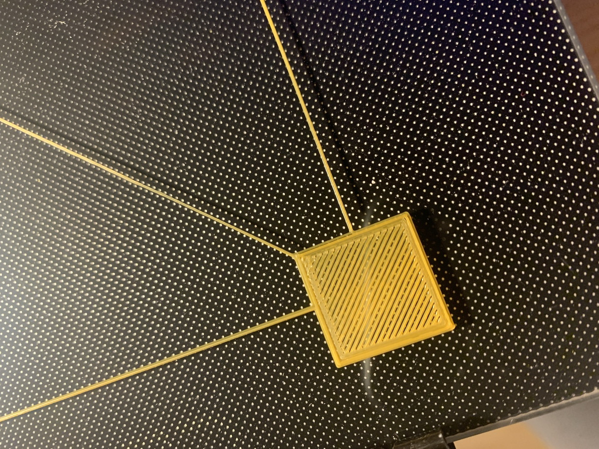
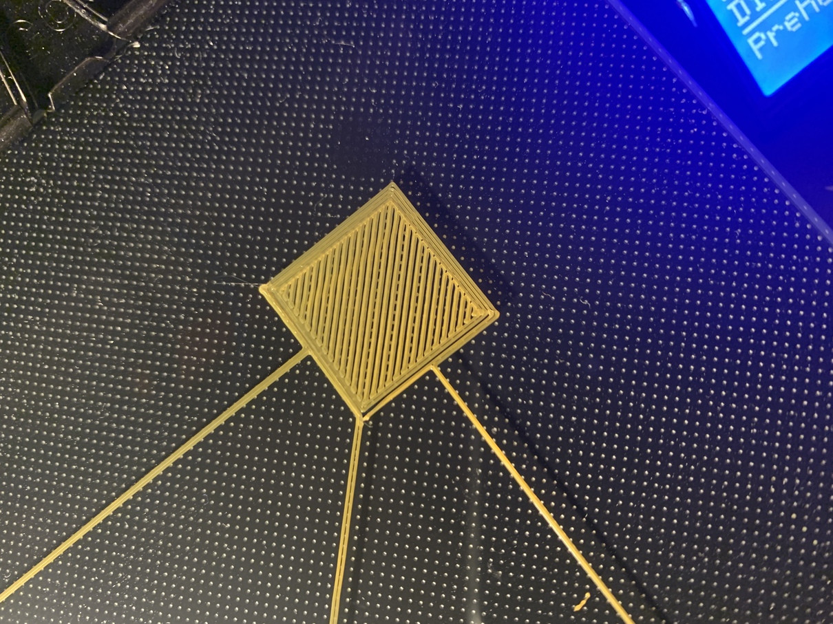
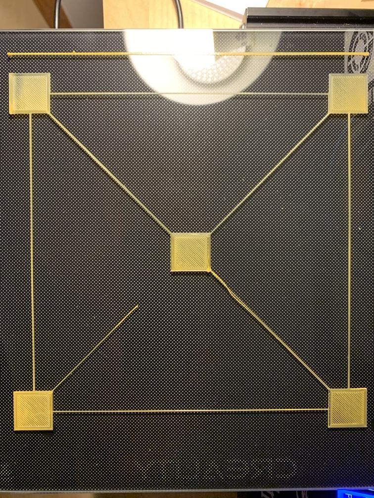
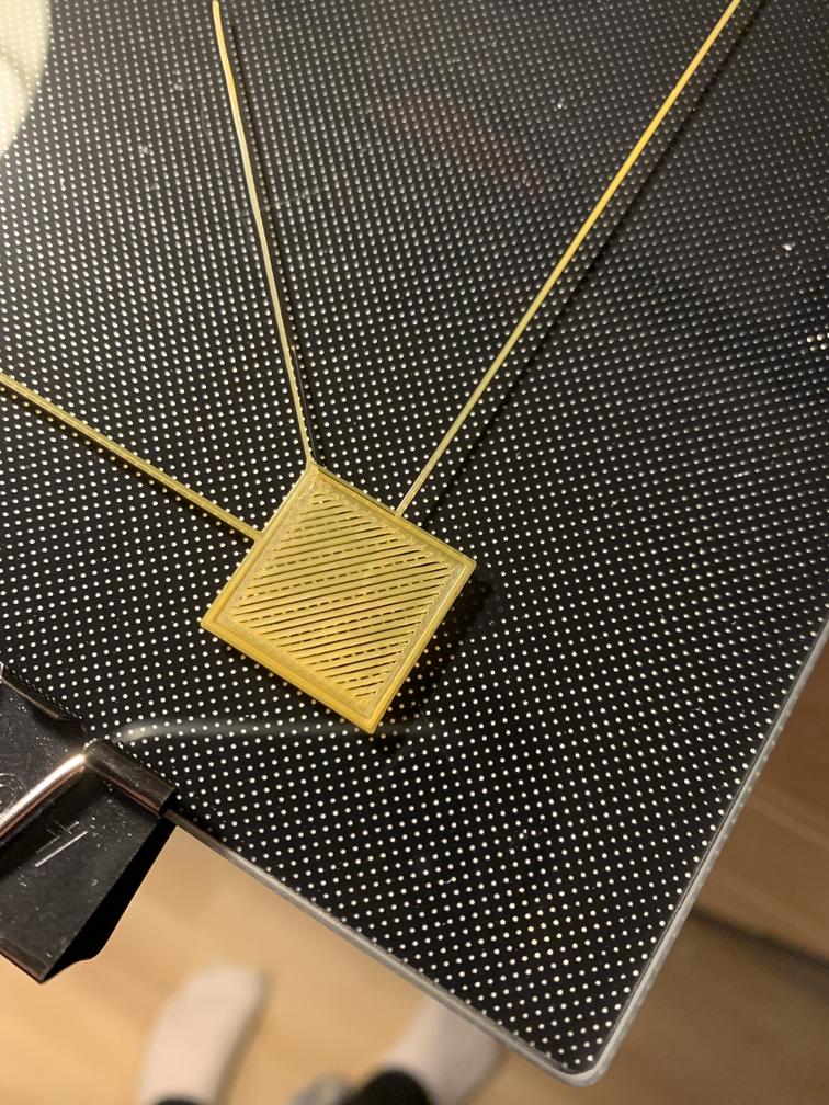
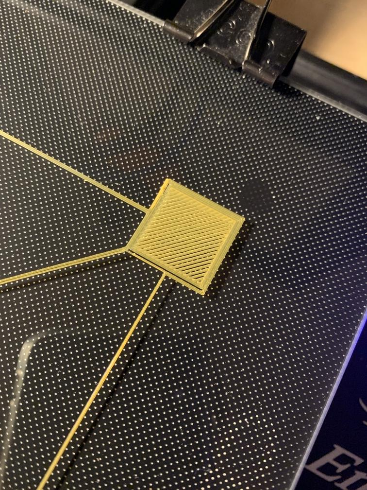
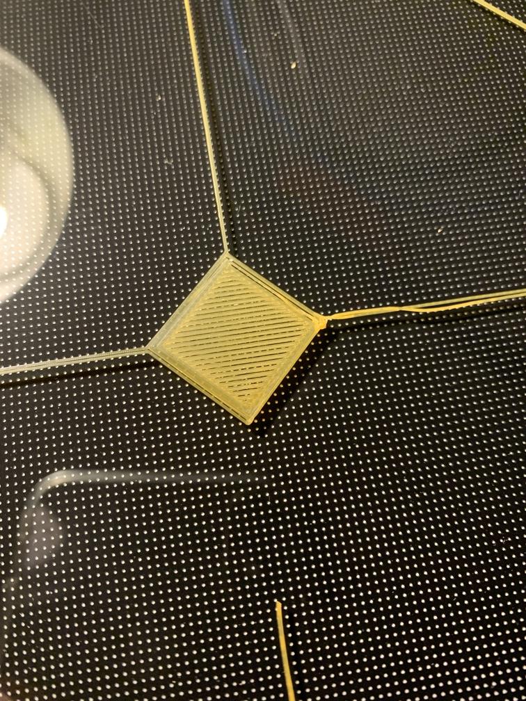
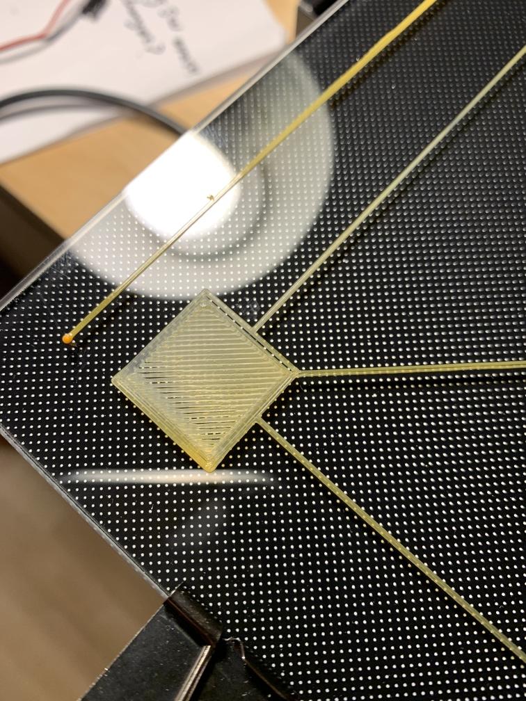
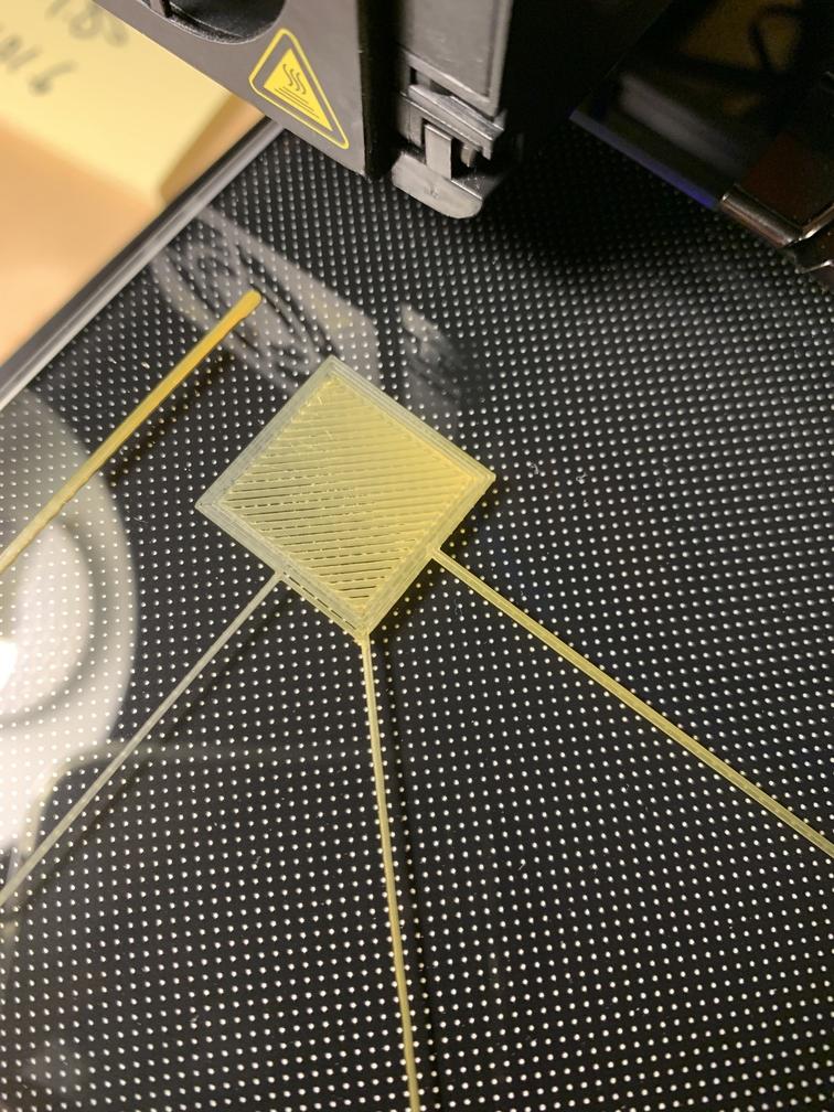
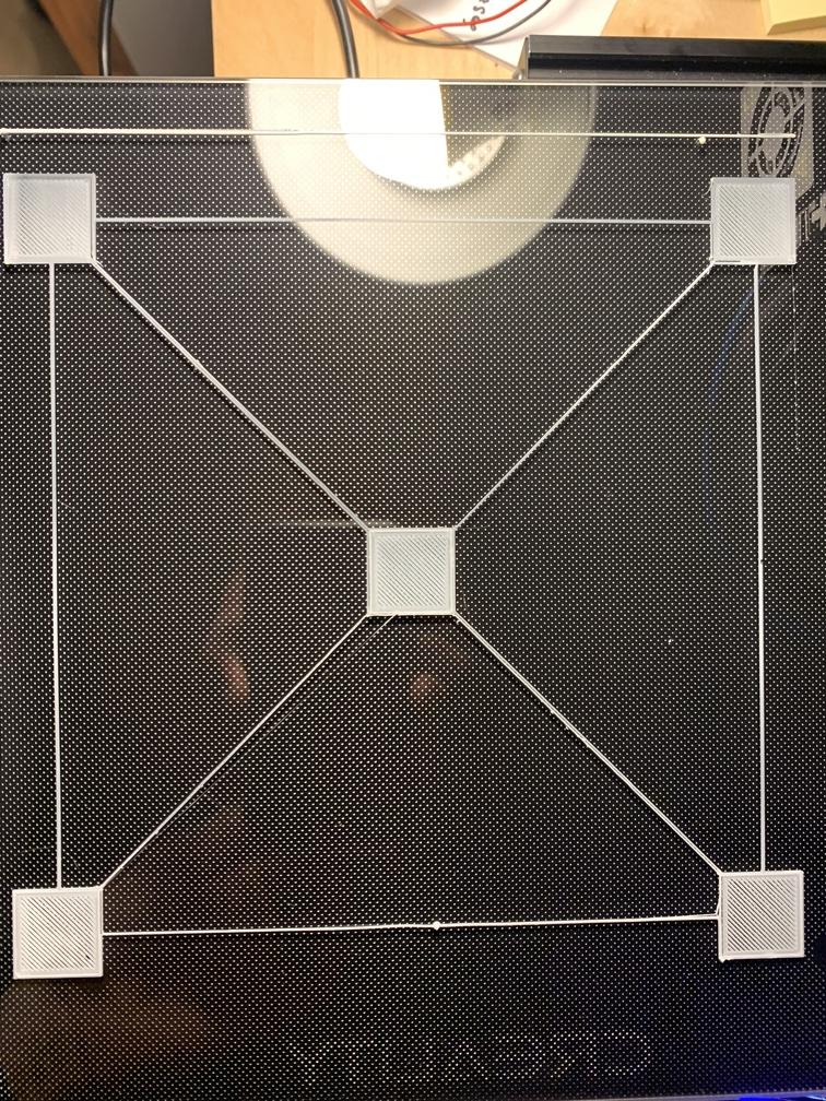
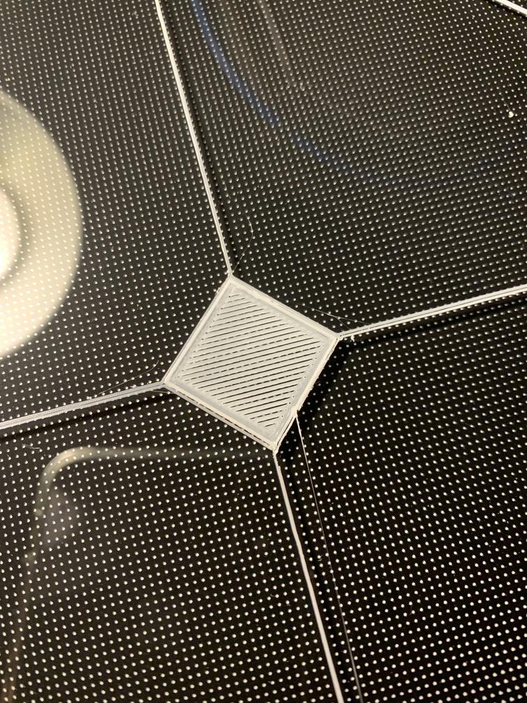
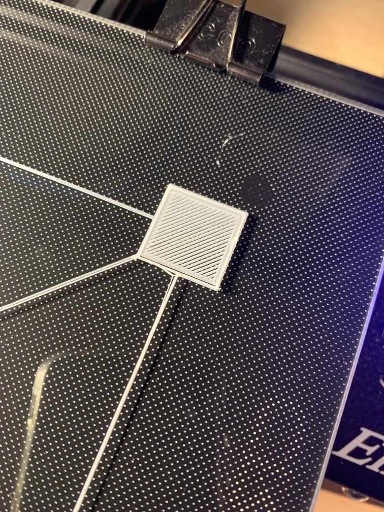
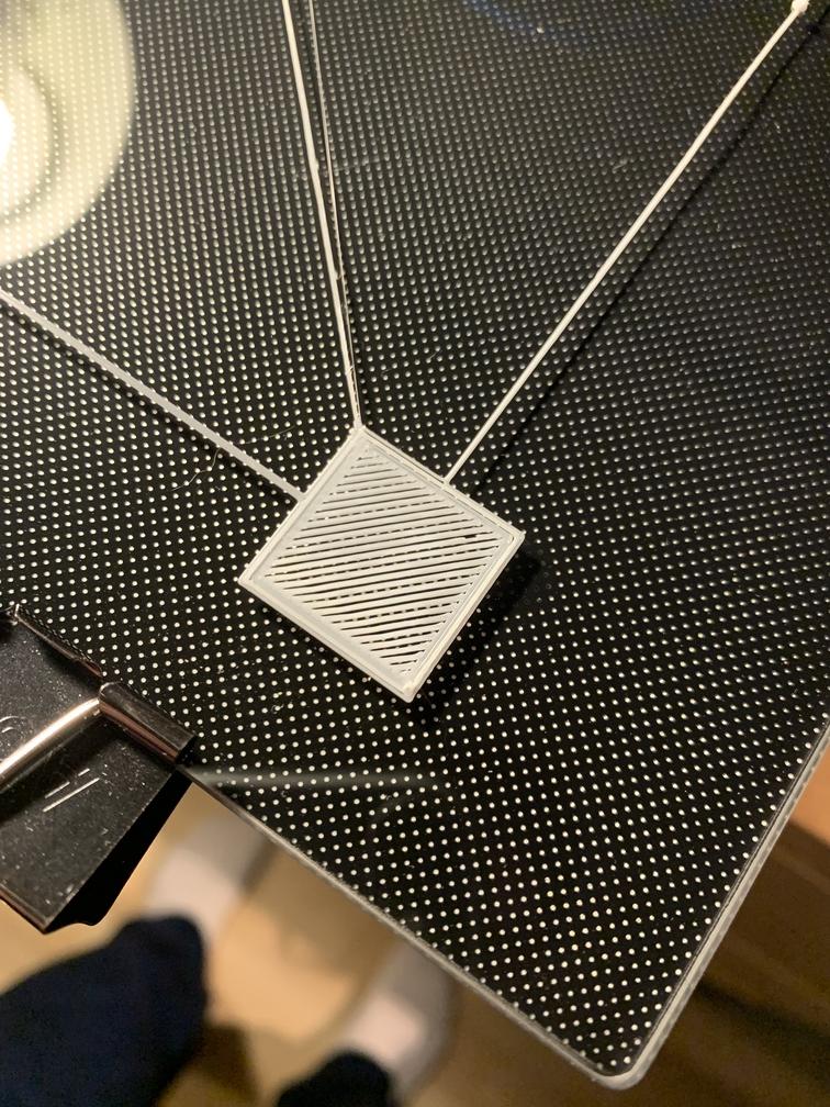
After doing this, I added G29 after G28 in my starting G-Code in Cura. I sliced a model from Thingiverse that had 5 squares and some lines. Here are the results:
I am using:
- Filament : PLA
- Bed Temp : 60 °C
- Nozzle Temp : 200 °C
Some miscellaneous notes:
- The bed was cleaned thoroughly prior to use
- I rotated the bed 90° and the print looked the exact same way
- I ensured that the bed soaked in some heat for some time prior to printing
- I have set my Z offset to -1.800 mm
- The frame and components seem to be square and tightened down. Nothing is shaking around and seems to be in order.
I would really appreciate help on this. I'm really not sure what to do next. I've been really excited about 3D printing and I hope I can find a solution to this.
Leveling using CHEP's video
So I have rebuilt my 3D printer using CHEP's video. I noticed that one or two things were off compared to how it was supposed to be. I will be doing some test prints to see if that actually fixed things. I am hopeful.
I did a mesh before any other changes, and the slant is very clear now. See below. I believe one of the plates on the gantry wasn't completely straight.
Leveling after rebuilding printer
Here is my latest mesh, after rebuilding the printer and then re-levelling its bed manually.
These are the results of the print. I had to change my Z offset to -1.60 mm. The broken line is my fault. It was caused by my finger. The focus is the corners. As I mentioned, this is after rebuilding my printer.
Edit
I would like to have more probing points than Creality's 3x3 grid. To my understanding, Creality's source code is not available, and so I will be rolling my own with Marlin 2.0. I downloaded the latest Marlin from https://github.com/MarlinFirmware/Marlin/releases, and copied the 4.2.2 Creality configuration from the default Configurations. I then changed the following:
- I ensured
#define PDITEMPis not commented so that I can do PID tuning of the nozzle. - Similar to 1., I ensured that
#define PIDTEMPBEDis not commented so that I can do PID tuning of the bed. - I commented
#define Z_MIN_PROBE_USES_Z_MIN_ENDSTOP_PINsince I will be using the 5-pin BLTouch port that is on my 4.2.2. board. - I uncommented
#define USE_PROBE_FOR_Z_HOMINGsince I removed my z-axis endstop and want to use my 3DTouch as the z endstop. - Uncommented
#define BLTOUCHsince the 3DTouch is a BLTouch clone. - Changed my x and y offsets in the setting
#define NOZZLE_TO_PROBE_OFFSET { -42, -8, 0 }. I left the z-offset 0, since I will be using the tuning tool to adjust that and observe the squish. For the x and y, I measured the distance between my probe and the nozzle using a digital caliper. - I adjusted the probe margin from 10 to 15, since I have clips that previously would interfere with the 3DTouch. 15 should give more distance.
#define PROBING_MARGIN 15 - I enabled and set MULTIPLE_PROBING to 3. I'm paranoid about the current accuracy, and am willing to see if that improves anything at the expense of a few additional minutes.
#define MULTIPLE_PROBING 3. I think 2 should be fine for general use. - Uncommented
#define Z_MIN_PROBE_REPEATABILITY_TEST. I want to test my 3DTouch and uncommenting allows the use of M48 to test it. - Uncommented
#define PROBING_FANS_OFF,#define PROBING_ESTEPPERS_OFF,#define PROBING_STEPPERS_OFF,#define DELAY_BEFORE_PROBING 200. The documentation this may improve probing results. I'm all in. - Uncommented
#define NO_MOTION_BEFORE_HOMINGand#define HOME_AFTER_DEACTIVATE. - Uncommented
#define AUTO_BED_LEVELING_BILINEAR - Uncommented
#define RESTORE_LEVELING_AFTER_G28. This is to ensure the mesh is applied even after G28, which disables the mesh otherwise. - Ensures that this setting was 10.
#define DEFAULT_LEVELING_FADE_HEIGHT 10.0 - I set the following :
#define GRID_MAX_POINTS_X 7. Ensures a 7x7 mesh grid is created. This could be more or less. 49 points is an improvement over Creality's 9, although a bit much. Worthwhile in my case. - Uncommented
#define EXTRAPOLATE_BEYOND_GRID. I was actually wondering if this was causing some of the inconsistent prints near the edge. - Uncommented
#define LCD_BED_LEVELING. This is to unlock more options for ABL in the menu. - Uncommented
#define LEVEL_BED_CORNERS. This should make moving between corners for manual levelling easier. - Uncommented
#define LEVEL_CORNERS_USE_PROBE. This is to achieve exactly what I was doing with G30 in Pronterface. I changed to tolerance with#define LEVEL_CORNERS_PROBE_TOLERANCE 0.03 - Uncommented
#define Z_SAFE_HOMING, which is important for the BLTouch. - Changed my PLA profile according to what I have determined to be best with
#define PREHEAT_1_TEMP_HOTEND 200and#define PREHEAT_1_TEMP_BED 60
I had to comment #define BLTOUCH_SET_5V_MODE for things to compile. I also had to modify #define LEVEL_CORNERS_INSET_LFRB { 30, 30, 45, 45 }, due to the margin I set as well as the offset of my touch. Otherwise, the above configuration was fine, in terms of compilation.
I'll post back with the results.
Here are the results for the M48 3DTouch test. Are these values good?
| Measurement | Value |
|---|---|
| Mean | 0.063667 |
| Min | 0.061 |
| Max | 0.068 |
| Range | 0.007 |
| STD | 0.002478 |
I reduced the speed of the probing in half in order to make the probing more accurate. This was done by changing from #define Z_PROBE_FEEDRATE_FAST (4*60) to #define Z_PROBE_FEEDRATE_FAST (2*60). I also made the mesh grid 8x8 because might as well.
These are my M48 repeatability results. Interesting to compare to the above table which probed at double the speed.
| Measurement | Value |
|---|---|
| Mean | 0.005500 |
| Min | 0.002 |
| Max | 0.010 |
| Range | 0.008 |
| STD | 0.001908 |
I also changed the filament (brand new). Just as another variable to modify.
The following prints are the result.
The mesh before this print is as follows:
Levelling the X-Axis Gantry
As Oscar in the comments has mentioned, I have read some other forum posts that described the cause of uneven lines and similar inconsistencies as what I am noticing, as being due to the X-axis Gantry that moves up and down as not being level.
I used a digital caliper and measured the x axis gantry relative to the frame of the 3D printer. So for example, I put my caliper against the base metal extrusion and then against the x-axis gantry. I did this on both sides.
The side without the Z-Axis lead screw (right side) was above the side with the Z-Axis lead screw (left side) by about 1.7mm. I'm surprised that CHEP and some other build videos never mentioned to check this, but it does seem logical to consider. Making the brackets flush is NOT adequate. When I do make it flush, then one side is higher than the other. The build videos say to make it flush. This will make things OFF.
To adjust this, I took off the gantry, slightly loosened the bolts on both side plates, so that it was stiff enough that it wouldn't move easily, but could make subtle adjustments by twisting it hard enough. I then put the gantry back on the printer, did some measurements and corresponding adjustments. I then carefully threaded the gantry off and tightened the plates.
Currently, my left and right side have a difference of .17mm. I figured I won't get anything better by hand. I'll do another test print tonight. 1.7mm vs .17mm is a reasonable difference.
