7
$\begingroup$

I want to know the math behind how Slic3r calculates E values. $E_{value}$ represents amount of filament in mm (unless volumetric extrusion is selected) that has to be fed into the hotend to obtain a road of specific extrusion width.

Consider an example with following parameters:

  • Nozzle diameter = 0.6 mm
  • Layer height = 0.35 mm
  • Extrusion width = 0.61 mm (for external perimeter)
  • Length of the line segment (distance of the deposition path) = 98.2 mm
  • Diameter of filament = 1.75 mm

First part of the question: How is $E_{value}$ calculated for this case?

Second part of the question: How is velocity of extruder motor calculated for this case?

The Slic3r manual has limited information on flow math but is not comprehensive.

Let's assume volume of plastic fed in equal volume of plastic comes out

$$Volume_{in} = \pi\times{(\frac{d}{2})}^2 \times E \times x = \frac{\pi\cdot d^2}{4}\times E \times x$$

Where,

  • $d$ = diameter of the filament
  • $x$ = extrusion multiplier
  • $E$ = $E_{value}$ to solve for

$$Volume_{out} = (A_{road} \times L)$$

  • Length of path, $L$, is obtained from start and end coordinates

  • Area of the road, $A_{road}$, is calculated according to this link (Slic3r flow math; Section: Extruding on top of a surface). The formula for area of the road according to Slic3r manual is:

$$A_{road} = (w - h)\times h + \pi\times{(\frac{h}{2})}^2 $$

Where,

  • $w$ = Extrusion width
  • $h$ = layer height

Seems like I am missing something. Math doesn't yield me same result as Slic3r $E$ value.


Many of you have marked this question duplicate. I know the first question is similar to what has asked before (calculating E value) but the answer doesn't match actual E value in G-code.

Also there is a second question on how to calculate extrusion speed given an E value

I have added G-code from actual Slic3r with the same settings as above to check the math.

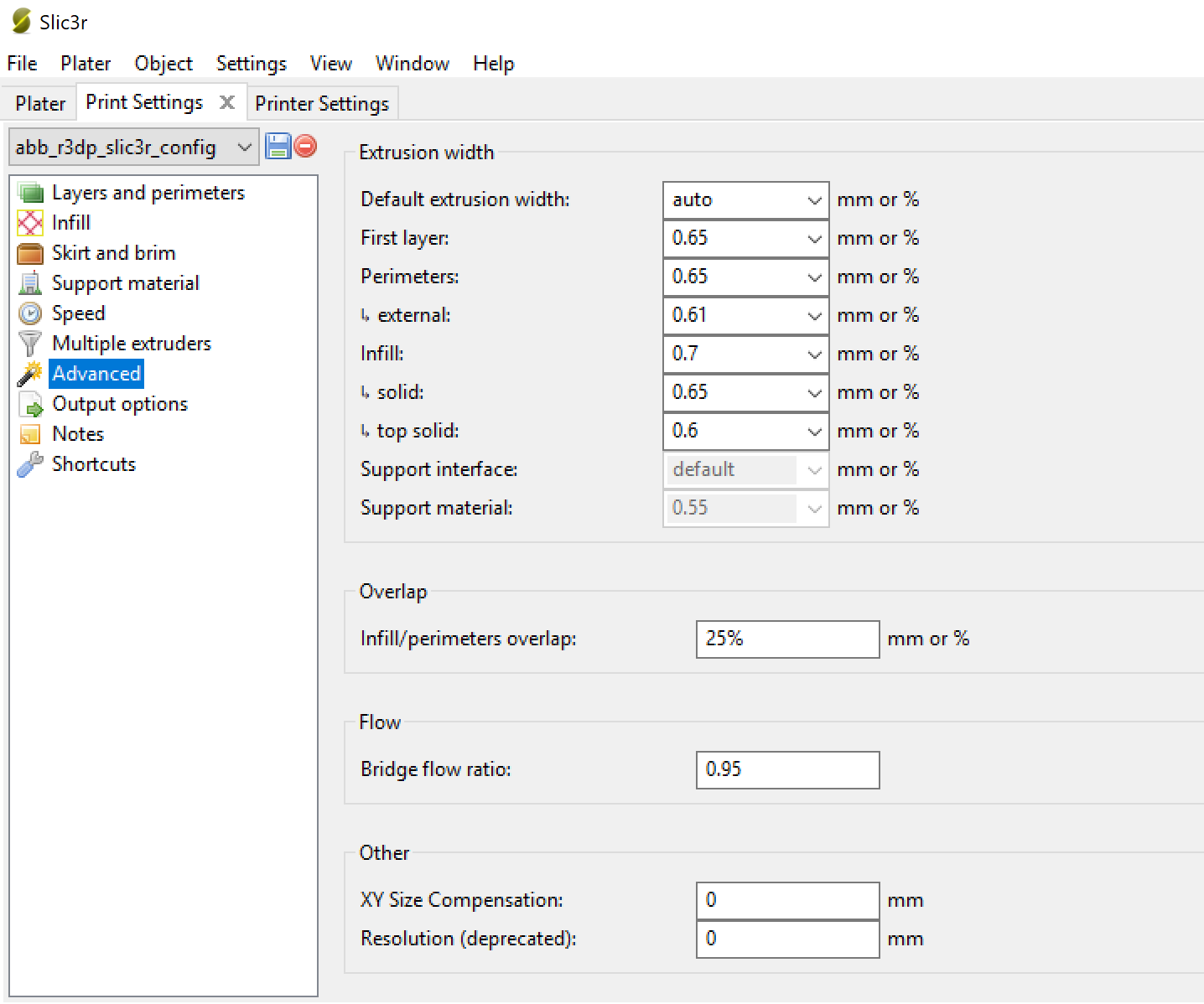
The advance extrusion width settings in slic3r are as shown in the picture below: enter image description here The settings are from a Prusa config for 0.6 mm nozzle
Consider a 100 mm x 100 mm x 5 mm part (X x Y x Z dimensions). Following is the output G-code from Slic3r:

; generated by Slic3r 1.3.0 on 2019-06-04 at 16:36:24

; external perimeters extrusion width = 0.61mm (6.55mm^3/s)

; perimeters extrusion width = 0.65mm (10.54mm^3/s)

; infill extrusion width = 0.70mm (15.25mm^3/s)

; solid infill extrusion width = 0.65mm (8.78mm^3/s)

; top infill extrusion width = 0.60mm (6.43mm^3/s)

------ Values of parameters defined in Slic3r -------

  • first_layer_acceleration = 1000
  • first_layer_bed_temperature = 60
  • first_layer_extrusion_width = 0.65
  • first_layer_speed = 30
  • first_layer_temperature = 215
  • first_layer_height = 0.35
  • max_print_speed = 100
  • nozzle_diameter = 0.6
  • external_perimeter_extrusion_width = 0.61

------ some initialization lines above --------

G1 F1800

G1 X78.400 Y169.100 E8.21483 ; perimeter

**G1 X78.400 Y70.900 E8.21483 ; perimeter**

G1 X176.600 Y70.900 E8.21483 ; perimeter

G1 X176.600 Y169.010 E8.20731 ; perimeter

G1 X177.175 Y169.675 F10800.000 ; move to first perimeter point

The above code snippet refers to the perimeter of the very first layer in the print. Let us consider the highlighted line in above G-code. According to equations we have above, the values of the variables are:

  • $d$ = 1.75
  • $x$ = 1
  • $E$ = $E_{value}$ to solve for
  • $w$ = 0.61
  • $h$ = 0.35
  • $L$ = 169.100 - 70.900 = 98.2

Area of the depositied road is:

$$A_{road} = (0.61 - 0.35)\times 0.35 + \pi\times{(\frac{0.35}{2})}^2 $$ $$A_{road} = 0.187211 mm^2 $$

For calculating $E_{value}$, We use volume equality

$$Volume_{in} = Volume_{out}$$

$$E_{value} = \frac{A\times L \times 4} {\pi\times d^2 \times x} = \frac{0.187211 \times 98.2 \times 4} {\pi \times 1.75^2 \times 1} = 7.6432 $$

The $E_{value}$ in the G-code is 8.214

This is a big difference isn't it? I know about the die swell effect and expansion of molten plastic at the tip, but there seems to be no uniform compensation factor for this!
$\endgroup$
4
  • 3
    $\begingroup$ Slic3r is open-source. You don't have to assume anything. $\endgroup$
    – Mick
    Commented Jun 4, 2019 at 5:23
  • 4
    $\begingroup$ Closely related to, but not duplicate of How is the E argument calculated for a given G1 command? $\endgroup$
    – 0scar
    Commented Jun 4, 2019 at 6:28
  • $\begingroup$ @Oscar, I saw this post earlier. still the calculations dont match with those of actual values output by slic3r $\endgroup$
    – Rock
    Commented Jun 4, 2019 at 13:48
  • $\begingroup$ @Rock It should, I've calculated it before in a different answer, it should match or at least very close as there might be some second order effects in play. You should edit the question with an example piece of G-code from slic3r and your calculation. Then we can verify it, now it is guess work. Bit still, the numbers should add up, fortunately, this isn't rocket science ;). A second order effect is die swell, the lines are thicker than the nozzle size on extrusion, there might be compensations in play. $\endgroup$
    – 0scar
    Commented Jun 4, 2019 at 16:57

1 Answer 1

4
$\begingroup$

To answer your first question:

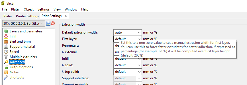
Your calculations are not wrong, they are correct for a normal layer (uncorrected) layer. These calculations should get you very near the solution. The problem is that there are default modifiers at play that modify the extrusion process which become apparent when you change them or look at the hoover hint in the advanced printer settings section. E.g. see the image below of the "Print Settings" graphical user interface; specifically look at the hoovering hint:

Slic3r Print Settings GUI

The hoovering hint tells you that there is a 200 % modifier at play. What! a default modifier without me knowing? Well...., if we had looked at the Slic3r Manual (The Important First Layer) a little better, we read that:

Fatter extrusion width.
The more material touching the bed, the better the object will adhere to it, and this can be achieved by increasing the extrusion width of the first layer, either by a percentage or a fixed amount. Any spaces between the extrusions are adjusted accordingly.

A value of approximately 200 % is usually recommended, but note that the value is calculated from the layer height and so the value should only be set if the layer height is the highest possible. For example, if the layer height is 0.1 mm, and the extrusion width is set to 200 %, then the actual extruded width will only be 0.2 mm, which is smaller than the nozzle. This would cause poor flow and lead to a failed print. It is therefore highly recommended to combine the high first layer height technique recommended above with this one. Setting the first layer height to 0.35 mm and the first extrusion width to 200 % would result in a nice fat extrusion 0.65 mm wide.

Tada! There we have the modifier from the screenshot; 200 % (this is expressed as a percentage over the layer height, and causes that an additional filament scale factor bigger than 1 is at play; the $x$ in your equations).

To answer the second question:

That should be rather straight forward, you know how long the path is and at which speed the head is moving (either at constant speed, decelerating or accelerating) and how much of filament you need to deposit, at the end point all filament needs to be deposited so you can calculate how fast the extrusion needs to be to accomplish that.


If you calculate back from a volume of 8.214 mm2 and solve for unknown $w$ you see that this yields $ w = 0.65\ mm $, and that is exactly what is stated as first layer width in your Slic3r settings; I quote:

first_layer_extrusion_width = 0.65


P.S. When you look into the source code of Slic3r, if you dig deep, you find that extrusion width is bound by minimum and maximum values, it could well be that that is causing the value to differ from 0.70 mm (200 % of 0.35).

$\endgroup$
8
  • 1
    $\begingroup$ Excellent..! :-) $\endgroup$
    – Greenonline
    Commented Jun 5, 2019 at 20:11
  • 1
    $\begingroup$ Very nice. I know it's a quote, but... "Setting the first layer height to 0.35 mm and the first extrusion width to 200 % would result in a nice fat extrusion 0.65 mm wide." - gets out calculator... $\endgroup$
    – Davo
    Commented Jun 5, 2019 at 20:42
  • 1
    $\begingroup$ @Davo Yep, my HP-48 G says 0.70, please don't shoot the messenger ;) $\endgroup$
    – 0scar
    Commented Jun 5, 2019 at 20:59
  • $\begingroup$ @0scar Thank you for the explanation. The calculations match up when I use extrusion width = 0.65mm. I checked my slic3r config (edited my original question to add the picture). I am using a config from Prusa for 0.6 mm nozzle. Although its not set to auto, the value still corresponds to 200% (default). What was throwing me off was that the lines of g-code in my question correspond to external perimeter and there is a specific value for external perimeter width for external perimeters (0.61 mm). Does, the "first layer" width overrides the perimeter width too? $\endgroup$
    – Rock
    Commented Jun 7, 2019 at 16:44
  • $\begingroup$ @Rock Yes first layer overrides other settings. $\endgroup$
    – 0scar
    Commented Jun 7, 2019 at 18:47

You must log in to answer this question.

Not the answer you're looking for? Browse other questions tagged .