1
$\begingroup$

In my custom printer I have probe and nozzle at same height and configured Marlin this way:

#define NOZZLE_TO_PROBE_OFFSET { 43, -20, 0 }

On the bed I've a 2 mm glass. How I need to change the configuration? Do I need to act adding a positive Z offset? like this?

#define NOZZLE_TO_PROBE_OFFSET { 43, -20, 2 }
$\endgroup$
1
  • $\begingroup$ You don't define the Z of this array definition. Actually the probe offset is not of interest at all; it is the probe trigger to bed distance that is of interest, this can be set using M851 Zx.xx or through the menu. $\endgroup$
    – 0scar
    Commented Mar 13, 2020 at 11:59

2 Answers 2

3
$\begingroup$

You can define the probe offset (or better the trigger point to bed level distance) in the array definition of NOZZLE_TO_PROBE_OFFSET, but it is not the usual and logical place to do that. Instead you position the probe higher than the nozzle and define the offset later when calibrating the bed level. A positive value is a positive offset, Z+.


This answer is intended to be a more generic answer for Z-offset determination. The question is not clear on what kind of Z-probe is used. In case of a touch (or an inductive or a capacitive) probe, a probe trigger point defines how far the probe needs to be from the bed level (the sensor is always placed higher than the nozzle). This trigger point is a measure for the offset and used to determine the distance of the nozzle to the bed print surface (using the offset). Correct installation is trivial, as is the determination of the nozzle to trigger point definition. For a touch sensor, the probing element is either stowed, fully deployed, or pushed in during leveling up to the point that the trigger point is reached and the probe stowes the rest of the pin, see figure:
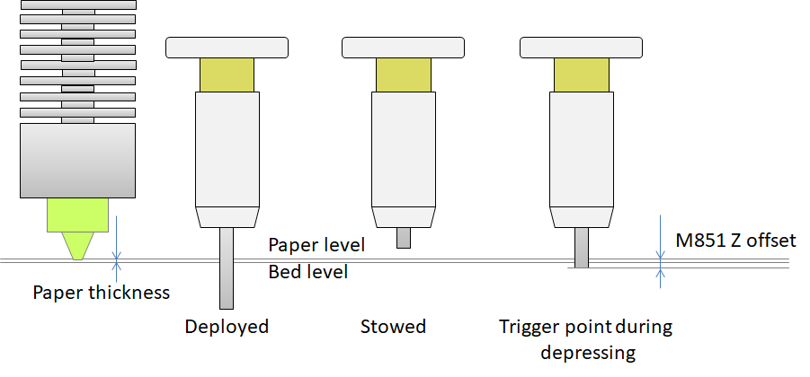
BLTouch or 3DTouch sensor Z-offset definition

The M851 Zxx.xx offset is determined by lowering the nozzle beyond the trigger point until the nozzle hits a sheet of paper. If the stowed position to nozzle distance is used, the distance is too large and the nozzle will dive into the bed on printing. A similar sketch for inductive/capacitive proximity probes can be drawn.
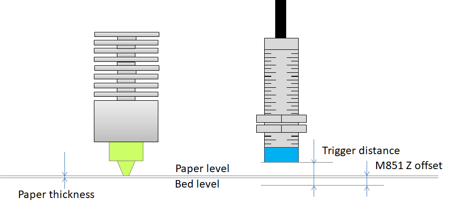
Inductive/capacitive proximity sensor Z-offset definition

$\endgroup$
1
  • $\begingroup$ When setting this up, I had to negate the Z offset. The process I followed was the same as described, lower nozzle until it touches the paper. But once you get the paper to touch the nozzle, you take the z reading and negate it thus giving you your Z Probe Offset. $\endgroup$
    – Lucas B
    Commented Apr 19, 2021 at 21:53
1
$\begingroup$

No.

You define the Z-Value of the Nozzle to Probe offset mainly to get avoidance of collisions, but it is checked nowhere in the firmware code at all. Usually, the probe is mounted a millimeter or so above the nozzle anyway: you mount it in such a fashion that it triggers when the nozzle has the correct distance to the bed.

If you alter the bed by altering the distance between the nozzle and the metal part of the bed, you might need to alter the physical position of the probe to get the printer to trigger at the correct height, but you don't necessarily need to add a Z-offset.

You might, however, want to include it in the slicer for the case you want to print items in a sequence, which forces most slicers to try to do an error-avoidance pattern.

$\endgroup$

You must log in to answer this question.

Not the answer you're looking for? Browse other questions tagged .