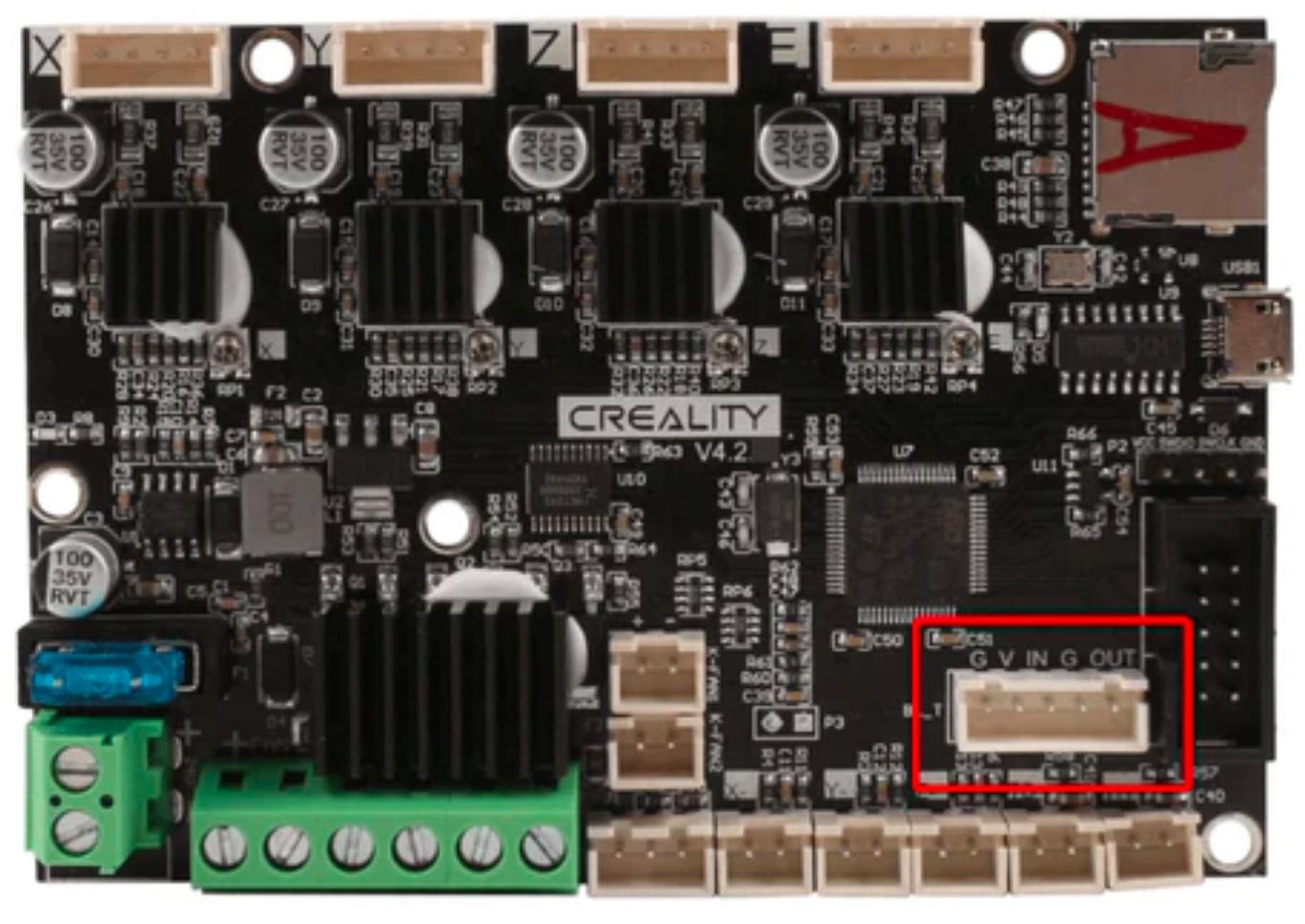
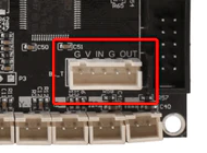
TL; DR - The pins are clearly named in reverse, and the IN pin is obviously an output and the OUT pin is obviously an input.
However, as to the why, it would be hard to guess, apart from the lazy deduction of either:
- Sloppy design work, or;
- Translation/language difficulties/barriers.
Without one of the board's designers posting an answer here, I guess we will never know for sure. A more generic labelling of both of the pins, such as IO1 and IO2, would have been better, and less confusing.
In addition, the guide, where the image that you posted comes from, seems to be rather poorly written and I would caution you against following it - see below for more details.
Notes
I may be wrong but the image that you show is presumably from this guide, Creality V4.2.2 & V4.2.7 Motherboard BL Touch Wiring Options, which shows two differing wiring suggestions (5 wire and 3+2 wire).
The 5 wire
A BLTouch with a 5 pin connector attaches to the 5 pin socket on the controller board:
original image
The 3+2 wire
A BLTouch with both a 3 pin and a 2 pin connector attaches to part of the 5 pin socket (the three left most pins, G, V and IN) and the Z-axis minimum endstop (Z-), respectively:
original image
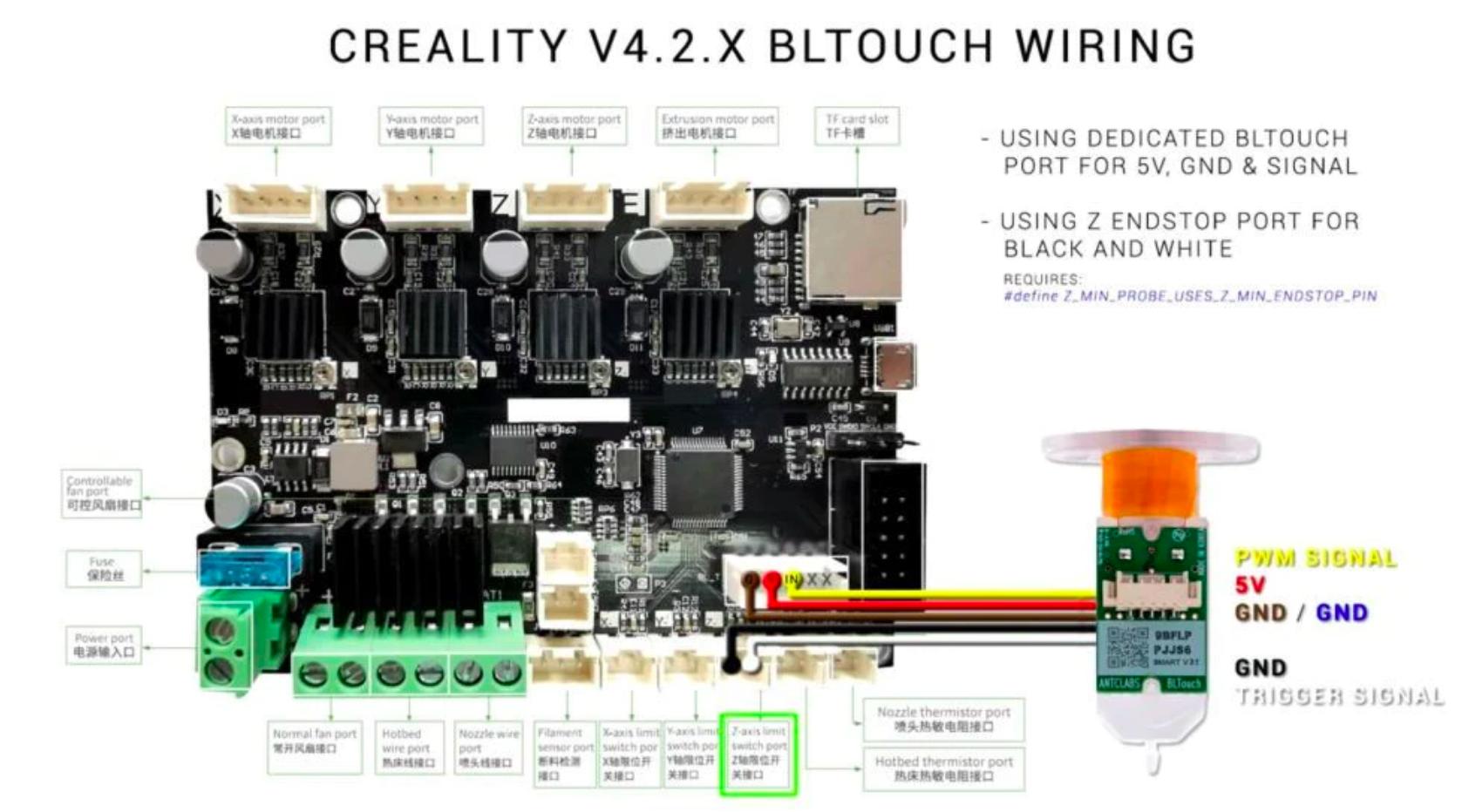
Note: If the image is expanded and examined carefully, it can be seen that "IN" has actually been written on the diagram, just over the yellow wire - obviously this is just a blind repetition of the mis-labelled pin.
Deduction
Either the z-axis endstop or the right most two pins of the 5 pin connector (G and OUT) can be used to connect the BLTouch probe sensor.
The right most connector (OUT) is therefore equivalent to the endstop pin, and is (most probably) an active low input, using a pull-up resistor either on the board or internal to the MCU - even though it is labelled as OUT.
This leaves the remaining connector (the three left most pins) for the BLTouch motor/servo. Therefore, obviously, the IN pin is actually an output used to actuate the motor/servo.
Note: As dandavis points out in their comment, the IO pins of the MCU IC are configurable in the firmware, and so could be reconfigured as either inputs or outputs.
Alternative 3+2 wiring
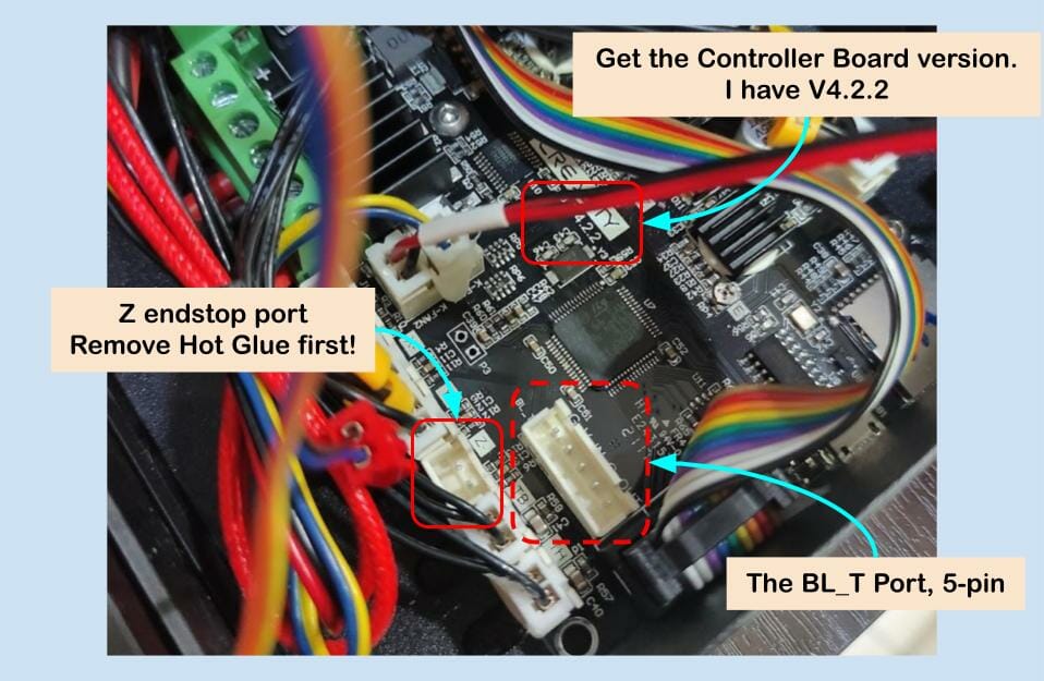
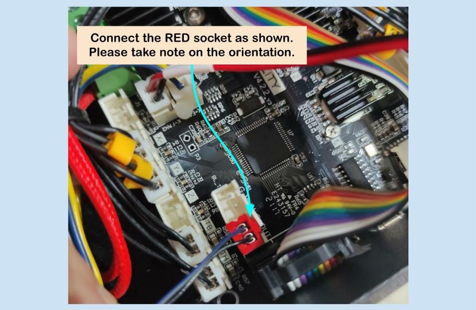
The much more useful and detailed tutorial, BLTouch Installation for Ender 3 with 32-bit V4.2.2 Board (linked to by towe in their comment) shows a similar set of connections, except that the 5 pin plug is replaced by the dual 3+2 wire connector, with both plugs (the 3 pin and the 2 pin) connected to the 5 pin socket on the controller board (rather than having the 2 pin going to the Z-axis endstop connector, as shown in the previous guide):
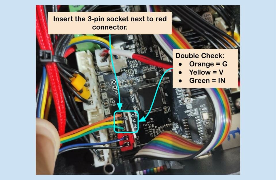
Enhanced 3+2 diagram and wire swapping warning - 32-bit board only
A better diagram of the 3+2 wiring configuration is shown below:
(original image)

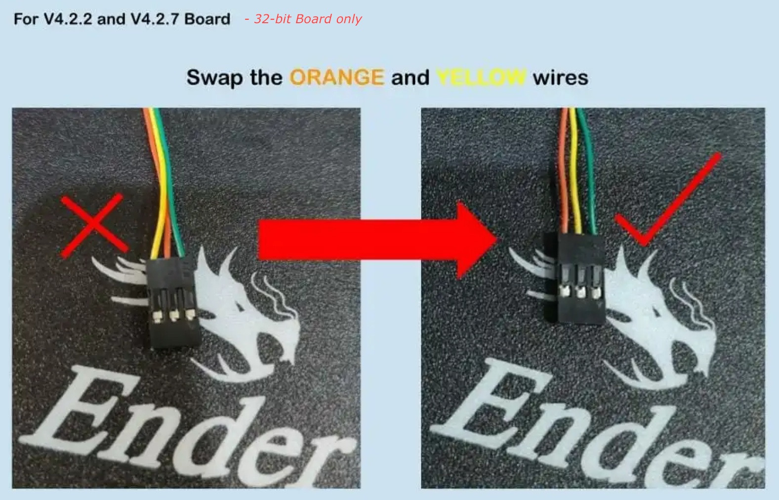
I found this diagram via the cautionary tale, Creality v4.2.2 board and BLtouch problem - board fried! on Reddit, which highlights the mismatch of the wiring of the various BLTouch probe/MoBo versions (the V and G pins may need to be swapped on the servo connector and must be verified before connecting and powering).
This mismatch, for the 32-bit board is also highlighted in BLTouch Installation for Ender 3 with 32-bit V4.2.2 Board, under the Swap the Wiring section:
This BLTouch Kit is meant for 8-bit and 32-bit board, however, the default wiring is for 8-bit (green) board with adapter (hack the buzzer pin for LCD). No swapping of wires is neccessary for 8-bit board.
For 32-bit board, we will need to do a minor adjustment to the wiring. This is a MUST step, as the swapped wires are VCC (+ve 5VDC) and GND (0V). If you do not swap the wires, you will damage the BLTouch and it is not under warranty.
(original image)
Firmware
For the sake of completion, and because the guide where your image came from does not seem to be particularly well-written - the firmware will differ, depending upon where the probe sensor is connected to, i.e. the z-axis endstop connector or the right hand pins of the 5 pin socket.
Either a different pre-compiled firmware binary is required or (if compiling the firmware yourself) some lines need to be uncommented in the Marlin source code, in configuration.h - which, according to the first guide, are the following lines:
#define BLTOUCH
...
#define AUTO_BED_LEVELING_BILINEAR
...
#define RESTORE_LEVELING_AFTER_G28
However, I'm not convinced by that rather overly simplistic first guide, unless the right most two pins of the 5 pin socket and the Z-axis endstop pins are hard-wired together on the board, which may be possible, but seems unlikely. I would have assumed that some pin changes are required in the firmware (but I may be wrong).
Indeed, the far superior guide, How to Set Up Marlin & BLTouch for Auto-Bed Leveling, shows that those three lines are only for the bed-levelling settings and a multitude of other changes are required.
Of particular note, if the Z-axis endstop is not used and the G and OUT pins are used instead, then make sure that the following line is commented out:
#define Z_MIN_PROBE_USES_Z_MIN_ENDSTOP_PIN
and uncomment
#define Z_MIN_PROBE_ENDSTOP
There are a number of other lines that need modifying, which are beyond the scope of this answer. Please refer to this guide or some other well written guide.
References


IO1andIO2would have equally sufficed as names. The left IO pin (IN) is for the (servo?) motor, and the right IO pin (OUT) is for the switch (and is a surrogate for the Z-axis switch). I've found guides with differing connections. $\endgroup$