4
$\begingroup$

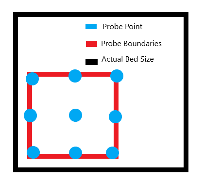
I have just installed the BLTouch on my Ender 3 running Marlin 1.1.9 and I want to set it up so the probing does the 9 points in a perimeter that uses most of the bed surface area. At the moment the probe just covers a small area.

enter image description here

I read that to sort it out you have to change the section " // Set the boundaries for probing (where the probe can reach)." but I can't figure out what to set it as, my current settings are as follows:

 #define LEFT_PROBE_BED_POSITION 30
 #define RIGHT_PROBE_BED_POSITION (X_BED_SIZE - 120)
 #define FRONT_PROBE_BED_POSITION 30
 #define BACK_PROBE_BED_POSITION (Y_BED_SIZE - 120)

When I try to set it so something like:

  #define LEFT_PROBE_BED_POSITION 30
  #define RIGHT_PROBE_BED_POSITION (X_BED_SIZE - 35)
  #define FRONT_PROBE_BED_POSITION 30
  #define BACK_PROBE_BED_POSITION (Y_BED_SIZE - 35)

I get an error reading :

  RIGHT PROBE_BED POSITION is outside the probe region.

Any help you can give me on what I am doing wrong will be greatly appreciated.

The probe offset from the extruder are as follows:

#define X_PROBE_OFFSET_FROM_EXTRUDER -41  // X offset: -left  +right  [of 
the nozzle]
#define Y_PROBE_OFFSET_FROM_EXTRUDER -5  // Y offset: -front +behind [the 
nozzle]
#define Z_PROBE_OFFSET_FROM_EXTRUDER -1  // Z offset: -below +above  [the 
nozzle]

For completeness, this is the G-code that I am using: CE3_square.gcode.
$\endgroup$
4
  • $\begingroup$ Please post the offset of probe with respect to the nozzle. That is #define X_PROBE_OFFSET_FROM_EXTRUDER and #define Y_PROBE_OFFSET_FROM_EXTRUDER $\endgroup$
    – 0scar
    Commented Nov 11, 2018 at 0:33
  • $\begingroup$ Please look into this answer and this answer. I think the latter answer answers your question. $\endgroup$
    – 0scar
    Commented Nov 11, 2018 at 0:45
  • 3
    $\begingroup$ Possible duplicate of Nozzle jumps off the bed when using Marlin Mesh Bed Leveling $\endgroup$
    – 0scar
    Commented Nov 11, 2018 at 0:47
  • $\begingroup$ I have edited the original post to include the extruder offset. $\endgroup$
    – Liam
    Commented Nov 11, 2018 at 0:50

1 Answer 1

5
$\begingroup$

As explained in this answer it is you that needs to calculate where the head (read sensor) is supposed to go depending on the amount of space you have left on the carriage shafts.

As can be seen from your configuration, your sensor is located on the left front (when facing the machine) at 41 mm left from the nozzle you are requesting the sensor to travel to a position that is outside the bed (35 mm), so you should at least subtract 41 mm from your X bed size.

As you have not posted a bed size, an assumed X bed size of 220 mm would mean that the maximum probing distance for X (i.e. RIGHT_PROBE_BED_POSITION) of 220 - 41 = 179 mm

In your case -41 mm would take it to the edge, so 30 mm extra would make it symmetrical:

#define LEFT_PROBE_BED_POSITION 30
#define RIGHT_PROBE_BED_POSITION (X_BED_SIZE - 41 - 30)
#define FRONT_PROBE_BED_POSITION 30
#define BACK_PROBE_BED_POSITION (Y_BED_SIZE - 5 - 30)

Furthermore, it is way more convenient to set the Z distance between the probe and the nozzle using M851 Zxx.xx (where xx.xx denotes the offset as a negative value) than setting it with Z_PROBE_OFFSET_FROM_EXTRUDER.

$\endgroup$
2
  • $\begingroup$ Thank you for helping, the probing is now the right size, however now my prints are off from the centre, a try to print line to make a square roughly 30mm from all the edges and it prints the front line right on the edge $\endgroup$
    – Liam
    Commented Nov 12, 2018 at 21:20
  • $\begingroup$ @Liam Great that you fixed the probing area. For centering: How to center my prints on the build platform? $\endgroup$
    – 0scar
    Commented Nov 12, 2018 at 21:34

You must log in to answer this question.

Not the answer you're looking for? Browse other questions tagged .