2
$\begingroup$

I am having a few problems with my BLTouch. I have calibrated it several times using different methods and get the nozzle being 1.3 mm lower than the BLTouch pin so a Z offset of -1.3 mm. This works fine for auto homing, bed levelling and using code G1 Z0 to lower to where needed. However when using Cura to print the nozzle homes exactly as it should then drives the nozzle in to the bed as it starts or tries to start to print and not just a little bit either. Anyone have any ideas?

Start G-code is:

G28 ;Home
G29 ;Probe
G1 Z15.0 F6000 ;Move Platform down 15 mm
G92 E0
G1 F200 E3
G92 E0
$\endgroup$
6
  • $\begingroup$ Hi MattW49, welcome to 3DPrinting.SE! Maybe you can share the first lines from a Cura sliced model up to the point it dives into the bed according to your observations. Furthermore please answer by edit: "Does this only happen with Cura (so not with other slicers)? Has it ever worked well? What steps did you use to calibrate the Z offset and store it in memory?" With more information people can provide better answers to help you out. $\endgroup$
    – 0scar
    Commented Sep 13, 2019 at 12:52
  • $\begingroup$ Could this answer on question "Specifying Z offset in Marlin firmware" be of assistance? $\endgroup$
    – 0scar
    Commented Sep 13, 2019 at 14:26
  • 1
    $\begingroup$ F6000 is too high, you will miss some steps. $\endgroup$ Commented Sep 17, 2019 at 4:30
  • $\begingroup$ What printer is this BL Touch on? Did it come as stock on that printer, or have you added it as an after-market mod? If the latter, did you flash the printer with new firmware? Which firmware build and how is it configured? $\endgroup$
    – Ty Hayes
    Commented Oct 21, 2019 at 13:58
  • $\begingroup$ Are you measuring the offset, so retracted with respect to the nozzle? If so, that is not how you do it, the actual distance (the triggerpoint to the nozzle distance should be used, this is a smaller value). If you use the measured distance, the value is too large and it will dive into the bed. $\endgroup$
    – 0scar
    Commented Feb 10, 2020 at 18:34

2 Answers 2

2
$\begingroup$

This answer is intended to be a generic answer for Z-offset determination. The question is not clear on how the Z-offset has been determined. It appears as if this distance is measured, while in reality this cannot be measured.

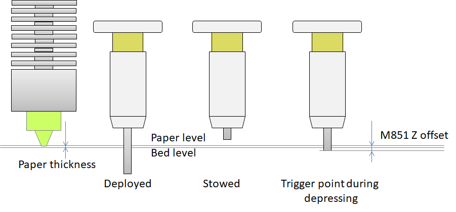
A touch (or a inductive or capacitive) probe uses a trigger point to determine the distance of the probe trigger point to the bed print surface. Correct installation is trivial, as is the determination of the nozzle to trigger point definition. For a touch sensor, the probing element is either stowed, fully deployed, or pushed in during leveling up to the point that the trigger point is reached and the probe stowes the rest of the pin, see figure:

BLTouch or 3DTouch sensor Z-offset definition

The M851 Zxx.xx offset is determined by lowering the nozzle beyond the trigger point until the nozzle hits a paper sheet. If the stowed position to nozzle distance is used, the distance is too large and the nozzle will dive into the bed on printing.

$\endgroup$
1
$\begingroup$

You should be able to offset this with a G54 Z-1.3 - if your setup accepts these gcodes.

If you do this, always add a G53 to the very start and just before the M30 to clear all offsets after job finish (or in the event of a cancel, at the start of the next job).

I'm not experienced with a wide variety of printers or firmware, but our repetier-based printers (and we use the same controls for our refurbished Fadal CNC machines) use G53-G59:

As explained in this tutorial from cnccookbook.com:

Basic work offsets are very simple to specify: simply enter one of G54, G55, G56, G57, G58, or G59. [...] When you execute the work offset g-code, the XYZ offset will be added to all of your coordinates from that point forward.

As detailed on Wikipedia:

G54-59: Have largely replaced position register (G50 and G92). Each tuple of axis offsets relates program zero directly to machine zero. Standard is 6 tuples (G54 to G59), with optional extensibility to 48 more via G54.1 P1 to P48.

And on the gcode dictionary provided by Hyrel 3D:

G54 through G59 - Set Offsets G54, G55, G56, G57, G58, and G59 will each store and invoke offsets in the X, Y, and/or Z axes for all subsequent moves. Any values not invoked will remain with their previous value (0 unless earlier specified otherwise).

  • X is the offset in mm in the X axis.
  • Y is the offset in mm in the Y axis.
  • Z is the offset in mm in the Z axis.

Here is an example:

G54 X100 Y-50

This command is decoded and executed by the printer as follows:

G54 (set offsets)
- X100 (+100mm to all X coordinates)
- Y-50 (-50mm to all Y coordinates)

Note that this differs from an M6, where the offsets are only applied to a SINGLE tool position.

Disclaimer: I work for Hyrel 3D.
$\endgroup$
2
  • 2
    $\begingroup$ G-code G54, is not listed in e.g. this G-code overview. Repetier does not support G54 according to the sources. This must be a custom firmware, not based on Repetier. And Marlin doesn't support the code either. I guess Hyrel is more onto CNC firmware. Thanks for the information! $\endgroup$
    – 0scar
    Commented Sep 13, 2019 at 20:25
  • 2
    $\begingroup$ We do our own firmware in-house, built on a repetier base. It's available from hyrel3d.com/wiki/index.php/New_Install but it is not open source and I don't expect it to work on non-hyrel equipment. We have our own interpreter, and run things more like a CNC. $\endgroup$
    – Davo
    Commented Sep 14, 2019 at 2:22

You must log in to answer this question.

Not the answer you're looking for? Browse other questions tagged .