1
$\begingroup$

When trying to solve the issue described in this post I followed the advice in the accepted answer and I found that the timing pulley holes for the Y axis (to "secure" the pulley to the motor shaft) were only half drilled (!!!). I suppose that everything worked fine (even without blind screws) for the first month (probably because the belt was extremely tight) but just a bit of wearing and it started to slip.

While I already replaced the pulley I also contacted the Creality technical support to obtain (at lest! funny...) a reassurance that it didn't possibly stressed the belt or the bearing balls. My experience with their technical support has been horrible and I am still waiting (after weeks) my answer (probably it's easier for them to try to ignore their sloppy assembly and QA) but they sent me a procedure to follow to "debug" any issue with my printer.

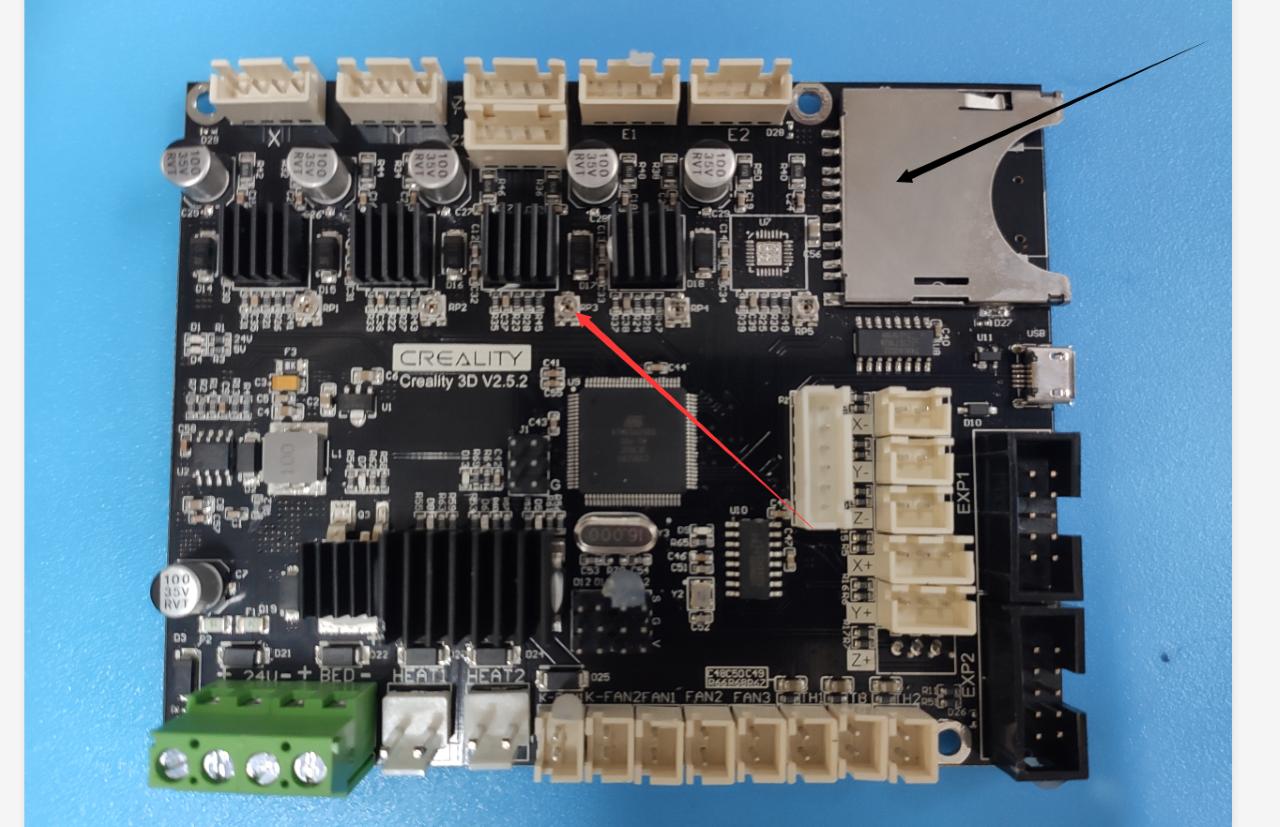
One of the pictures in that procedure is this:

What the CR-10S Pro V2 motherboard seems to be

To my surprise this is the motherboard I have:

What my motherboard looks like

Now I am puzzled. Which one is the correct motherboard for the Creality CR-10S Pro V2 (not the old version but the newer V2)? Is this just [another] sloppy mistake from the technical support or I do have the wrong motherboard? Differences with V1 are not many then I suppose it could even work with the old one...
$\endgroup$
8
  • 1
    $\begingroup$ Your appears to be the standard v2.4 board, which is correct for the Pro printers. The picture they send you is from a board for the normal CR-10 models (and Ender series), which do not feature the evil 30-pin connector of the Pro. $\endgroup$
    – towe
    Commented Nov 26, 2020 at 13:57
  • $\begingroup$ @towe thank you! Could you please post it as an answer? That pretty much answers my question!!! $\endgroup$ Commented Nov 26, 2020 at 14:40
  • $\begingroup$ Done. As for your original issue, those little potentiometers can be found on your board as well, and should work similarly to how they described it in your mail. The "lower left" drivers in your picture should be responsible for the Y axis, and the potentiometer can be used to adjust the steppers current / power. Since your pulley was identified as the main issue, I however would not bother adjusting that if you don't encounter different issues. $\endgroup$
    – towe
    Commented Nov 26, 2020 at 14:50
  • $\begingroup$ @towe yes, I just followed the labels on the cables and the values were what they said so I didn't need to change anything. Real issue seemed to be the timing pulley and I've already replaced that (slightly disappointed by the tech support but that's another story...maybe I just expect too much from a product of this price) $\endgroup$ Commented Nov 26, 2020 at 15:39
  • $\begingroup$ You'll get used to that level of "tech support". Except to identify and fix the issues yourself (or with the help of the community). Manufacturer support is mostly for getting the occasional free replacement part if they messed something up. $\endgroup$
    – towe
    Commented Nov 26, 2020 at 15:41

1 Answer 1

1
$\begingroup$

The board that's installed in your machine appears to be the Creality v2.4 / v2.4.1 board, which is the correct board for your printer. It is distinguishable by the 30-pin ribbon connector, which is used to connect to the rest of the printer.

The board in the tech support pictures is the v2.5.2 "silent board", designed for printers such as the non-Pro CR-10 series. It features two 10-pin connectors for the LCD screen. It also uses individual connectors for all functions, so, contrary to the "Pro" boards, is also easily swappable with aftermarket boards.

A third type of board (e.g. v1.1.5) exists, mostly for the Ender 3 series of printers, which features only one 10-pin connector for the display.

$\endgroup$

You must log in to answer this question.

Not the answer you're looking for? Browse other questions tagged .