9
$\begingroup$

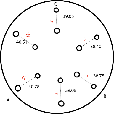
I have make a little test with 4 dots aligned with A tower, B and C tower. Distance W and S are the same in the stl but not in the print. I have tried diferent values of diagonal root but S always is smaller than W, and all S are equal (more or less 38.20mm) and all W are equal (more or less 40.80). I expect that W and S will be 40mm. How can fix this problem?

enter image description here

Update:

Here is the stl I use: https://www.dropbox.com/s/2vwjbo387cmk5qa/DeltaCalibration%20v15.stl?dl=0

Update: I have replaced the steper motor in tower B but same result.

$\endgroup$
4
  • $\begingroup$ Can you draw positions of the towers? What are the absolute values (expected and actual)? $\endgroup$
    – Mikhail Z
    Commented Sep 19, 2017 at 16:21
  • $\begingroup$ @MikhailZ I have updated the question with the towers position, actual and expected values. $\endgroup$
    – TlmaK0
    Commented Sep 19, 2017 at 16:36
  • $\begingroup$ Are your rods all the same length? $\endgroup$
    – Gunslinger
    Commented Sep 22, 2017 at 10:16
  • $\begingroup$ yes, I have checked again $\endgroup$
    – TlmaK0
    Commented Sep 22, 2017 at 10:23

2 Answers 2

4
+100
$\begingroup$

I bet your towers are not standing straight (vertical) or your bed is not clearly horizontal

I've recreated your picture with some assumptions (for example that your SW calculates properly and your steppers and motors act well).

Take a look here: enter image description here
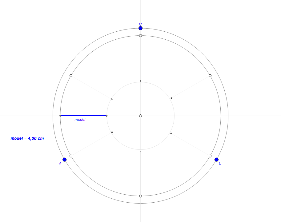
If you deliver your printer dimensions

  • tower height (from the base)
  • tower distance from the center
  • bed distance (height) from the base

I can calculate what the inclination angle on all towers is, but, I suppose it's not really important.

The important thing is to set them straight/vertical (perpendicular to the bed).

We can see from the picture that tower A is the most inclined to the center or the bed highest point is next to tower A (and I bet one of those or both cause the issue).

As an example, I've made some calculations based on imagined assuptions of the tower height here are details:

    towerH | inclination
-----------+----------------
    300 mm | 0.11°
    400 mm | 0.08°
    500 mm | 0.06°

It seems to be quite small but in fact your differences in dimensions are also small!

The inclination of tower B is bigger as there is bigger difference in dimensions, so maybe the issue is more in bed "horizontality".

It would be good if you would check and measure these parameters.

As for the explanation why bed the inclination causes dimension distortion:
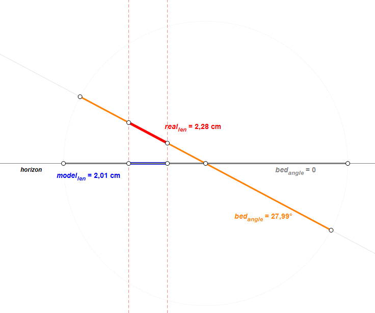
enter image description here

This is exaggerated but it's just to show the issue.
$\endgroup$
2
  • $\begingroup$ Thanks @darth_pixel!, the problem was the bed inclination. After fix it, I had to modify the end stop position, and the horizontal root length. I'm still having an issue with the C tower now, but I think It could be a problem with the printer frame. Could be great if you can explain why bed inclination and end stops affects to the accuracy. $\endgroup$
    – TlmaK0
    Commented Sep 26, 2017 at 11:32
  • $\begingroup$ @TlmaK0 take a look on edited post. to be honest i don't really know how endstops could have any influence on accuracy. no idea at all... well i would say it cannot have such influence ;) $\endgroup$ Commented Sep 26, 2017 at 12:22
2
$\begingroup$

Well, you have two main issues:

1.- Your calculation for stepping is a little wrong, for example your firmware indicates 2315.84 when you need 2321.70 (REMEMBER this is an example and is not accurate), So you will see a diference about 2.0mm along your printing. If your printing is bigger more diference you will get.

2.- Misalignment, your printer is not angled correctly to 90° and also Z axe if has the same condition. with this uncalibrated parameter are you going to have pisa towers on every tall part. For delta Printers this not apply

3.- Tension. Your belts are a little weak; avoid weak tension band to eliminate something called backslash, of course this is for screw parts but is the same efect and even bigger. Also you will get an accurate dimension of the parts.

$\endgroup$
5
  • $\begingroup$ thanks @fernando, what do you mean by calculation for stepping? I'm using repetier firmware, I didn't found any parameter like this. I have played with steps per mm, but same result, and the C tower has the same value up and down. I will check the tension band. $\endgroup$
    – TlmaK0
    Commented Sep 20, 2017 at 6:34
  • $\begingroup$ Backlash is not likely the case here as it produces quite different types of distortion, mostly visible when moving parts experience acceleration, for example, when printer head changes direction. $\endgroup$
    – Mikhail Z
    Commented Sep 20, 2017 at 10:30
  • $\begingroup$ Same problem after check the the belts $\endgroup$
    – TlmaK0
    Commented Sep 20, 2017 at 11:15
  • $\begingroup$ I´m trying to see repetier firmware due I´m using marlin for 3D printing and Gcode 1.0.6 for CNC but both handles X AXIS_STEPS_PER_MM 160 and Y AXIS_STEPS_PER_MM 160 and define ZAXIS_STEPS_PER_MM 2560 As example. So in Gcode sender I have to save the steps per mm; I don´t know if Repertier has an Eeprom to change this values. On Marlin this is the line to modify according your moving parts ** #define DEFAULT_AXIS_STEPS_PER_UNIT {78.7402,78.7402,200*8/3,760*1.1}** Where values are { X, Y, Z, E} $\endgroup$ Commented Sep 21, 2017 at 0:07
  • $\begingroup$ Number of steps for all axis in Delta printers must be the same $\endgroup$
    – Mikhail Z
    Commented Sep 21, 2017 at 9:20

You must log in to answer this question.

Not the answer you're looking for? Browse other questions tagged .