1
$\begingroup$

I found two great designs for a DIY sensor that achieve both filament runout and filament jam detection in one unit.

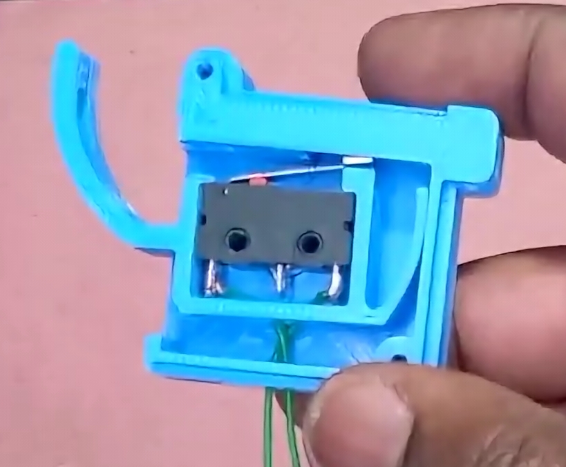
A clever design that only uses one microswitch as follows:

Filament runout and jam sensor with one microswitch

Source: Thingiverse.com

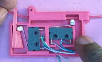
Another design using two microswitches, as follows:

Filament runout and jam sensor with two microswitches

Source: Thingiverse.com

I am not sure about the reliability of either yet, and I initially liked the design with one more switch. Then I realized there was no way to distinguish what event occurred (runout or jam), so I plan to make the second two microswitch versions instead. However, how would I wire this in a way so that my Ender 3 V2 running Marlin, specifically mriscoc firmware, would be able to interpret both signals separately and interpret them as two distinguishable events so that the exact event is reported (runout or jam)?

Alternatively, I could wire it to my Raspberry Pi, since I always print from OctoPrint only, and implement it there instead. However, I'd prefer to wire it to the printer board and have the firmware handle it.

Lastly, in comparison to these two specific designs, would an encoder wheel approach add benefits other than runout and jam detection?

Suggestions for better designs or approaches are also welcome.
$\endgroup$

2 Answers 2

2
$\begingroup$

Blue design

The blue design can only detect a lack of filament. It is boolean: Filament or No Filament.

Pink design

The pink design can have multiple states, combining two boolean values.

The right of the sensors is "Filament there".

The left is using a ramp. On pull along the ramp, the sensor is triggered once a certain amount of pull is overcome, either by pulling up, left or right. As a result of passing through the hole in the lever of known diameter. Any tangle or over thickness will act on the lever to the right and trigger the sensor, and so will strong yanking up or left, through those might self reset. As a result, this sensor will trigger a signal that could be called Tangle or No Tangle, or of course No Jam/Jam.

Your interpretation that there is no way to distinguish the results depends on one thing: that you put the sensors through a single loop back, for the effect of an AND gate.

Filament Jam Output of the Series
Filament in No Jam Run
Filament in Jam Stop
no Filament No Jam Stop
no Filament Jam Stop

The design is set up such, that the filament sensor shows connectivity on being pressed, while the jam sensor is connected in reverse: triggering it opens the loop. While the designer wired the two in parallel, they could also be connected in series for the same effect.

To overcome this design deficiency of only sending a stop message, you need to route the signal to your control board and distinguish the two signals. However, for all but the error message, the practical effect should be the same: the machine shall stop if either of the Stop conditions is triggered.

If you have other sensory equipment on the printer, you might quickly run into problems in that the number of free pins is usually extremely limited, so you might not have enough pins to route the signals separately.

is tangle trigger separate a good idea?

Now, is the additional requirement of pins and wiring a good idea when it comes to error handling? No.

In either detected case - no more filament or tangled filament - you need to stop printing and access the very same area to deal with the lack of feeding filament. Only in large operations, there is any reason to try and detect the two separately for logging purposes.

$\endgroup$
1
$\begingroup$

Both designs listed can detect runout and tangled filament. In both designs, the mechanics of detecting runout is for the filament presence to activate the switch while detecting tangle uses the tension between the reel and the extruder.

The tension mechanism has specific mounting requirements that other runout only sensors do not. It has to be fixed mounted to the printer frame so that the tension can act against it. And the tension arm should be oriented towards the filament reel which in this case is hanging over the printer. Different reel locations will require more thought. As an example, standalone reel holders that sit next to printers might not work if it is not heavy enough where the tension might drag or tip the reel.

The blue design is a well thought out optimization that relies on a rotating stage to pivot the switch away from the filament when the tension increases beyond the opposing spring tab. So a single switch will toggle with either runout or tension.

I agree with other answers that it is not necessary to differentiate between the two errors in firmware since both requires the same user intervention. If I was to implement separate detection anyways using the pink design, I would build a custom Marlin firmware that supports two runout sensors assuming I have enough controller pins to support a seconds input. (i.e. spare z end stop)

A third error that can use tension detection is a clogged/cold nozzle. This is tension that builds up after the extruder that is easy to detect on a Bowden setup. As the extruder tries to push a stuck filament, the net effect will try to elongate the Bowden tube. This can be detected as tension on the tube after the extruder. It is similar to examples on the Bambu tension monitor.

$\endgroup$

You must log in to answer this question.

Not the answer you're looking for? Browse other questions tagged .