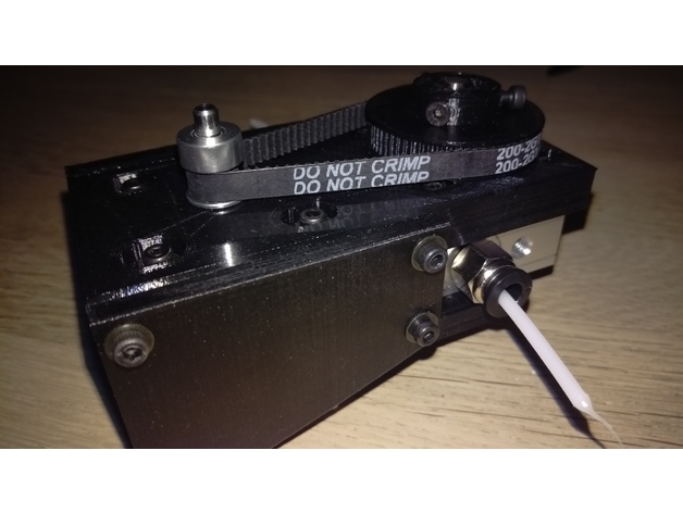
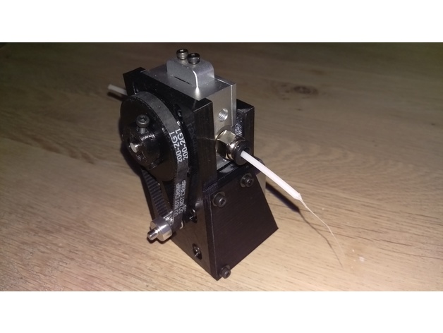
Most 3 mm (mostly are actually 2.85 mm) filament extruders have some kind of gear reduction. Many 1.75 mm extruders are direct-drive / ungeared but some do use gears. What kind of reduction ratios are suitable or optimal?
2 Answers
This basically depends on the torque your stepper can produce! A high torque stepper (the bigger the height of the stepper the more powerful the stepper) can push filament with much more force than a stepper motor with less torque. To increase the torque you employ a gear ratio to reduce the speed. As torque and speed are inversely proportional, a reduction by half in speed doubles the torque.
If your stepper is powerful enough, you can use a direct drive (no gearing) to push the filament. However if you want that same stepper to move filament of larger diameter, you might not have enough torque to do so. This means that you will have to increase the torque by employing a gear reduction. Using direct drive extruders thus require high torque, and thus high mass stepper motors, this causes the mass of the hotend carriage to increase considerably. Using stepper motors with less torque (often called pancake steppers because of their reduced height) for such applications is often seen together with a gear reduction. A drawback of reducing speed is that you also decrease the maximum print speed ability or max speed filament retraction speed. To reduce the speed you can use a gear reduction using gears or use pulleys and belts. A major advantage of a belt reduction is that it operates without much less noise than using gears.
Let us assume that you have a stepper that is powerful enough and want to extrude thicker diameter filament. The following guideline can be used to calculate the gear ratio. Also if you express the value in an actual torque, you could work your way back to calculate the gear reduction for a pancake stepper you would use to replace your current X-value torque motor, that is left as an exercise.
From 1.75 mm to 2.85 mm
Under the assumption that the force that the nozzle exerts on the build plate ($F_n$) is constant for different types of filament size, you would be able to calculate the ratio of force for the extruder ($F_{e}$) and nozzle of any filament diameter using the pressure in the nozzle using:
$$ p=\frac{F}{A} $$
Where, $p$ is the pressure, $F$ the force and $A$ the area.
$$ p =\frac{F_e}{A_e} = \frac{F_n}{A_n} \\ F_n=F_e\frac{A_e}{A_n}=F_{e_{1.75}}\frac{\frac{1}{4}\ \pi\ d_{1.75}^2}{\frac{1}{4}\ \pi\ d_{n}^2} = F_{e_{2.85}}\frac{\frac{1}{4}\ \pi\ d_{2.85}^2}{\frac{1}{4}\ \pi\ d_{n}^2} $$
Where $d$ denotes a diameter of the nozzle or the filament. Subscripts $e$ and $n$ denote the extruder and the nozzle respectively.
Note that the force that is generated by the extruder is derived from the stepper torque $\tau$ directly, or through a geared drive (gearing ratio $R_{gear}$ ):
$$ \tau_{e} = R_{gear}\times\tau_{stepper} $$ Note, a gear ratio of 1 denotes direct drive.
The force would then be calculated by dividing the torque by the radius ($r$) of the extruder gear:
$$ F=\frac{\tau_e}{r} $$
Combining equations gives us:
$$ \begin{align*} &1.75\ {filament}\ \Rightarrow F_n=\left (\frac{1\times\tau_{stepper}}{r_{e_{1.75}}}\right )\frac{d_{1.75}^2}{d_{n}^2} \\ &2.85\ {filament}\ \Rightarrow F_n=\left (\frac{R_{gear}\times\tau_{stepper}}{r_{e_{2.85}}}\right )\frac{d_{2.85}^2}{d_{n}^2} \end{align*} $$
Which can be rewritten to:
$$ R_{gear} = \frac{d_{1.75}^2}{d_{n}^2} \times \frac{d_{n}^2}{d_{2.85}^2} \times \frac{r_{e_{2.85}}}{r_{e_{1.75}}} $$
Note that each $d_{n}^2$ is applicable to the nozzle size of the extruder. Hence, for similar nozzle sizes, the $d_{n}^2$ term cancels out: $$ R_{gear} = \frac{d_{1.75}^2}{d_{2.85}^2} \times \frac{r_{e_{2.85}}}{r_{e_{1.75}}} $$
This means that if you go from 1.75 mm to 2.85 mm filament, for the exact same extruder gear radius (which is not likely as you probably need a different extruder gear/hobbed bolt that can accommodate the larger diameter filament), the gear ratio is $1:2.65$ and therefore you need to reduce the speed accordingly.
The reason that you see different gearing ratios can not only be explained by differences in the extruder gear/hobbed bolt diameter differences, but also in stepper torque values.
For 3 mm filament the ratio will be in the order of $1:2.94$ for equivalent extruder gear radii and reuse of the same stepper.
A similar calculation shows that for a 0.2 mm nozzle on a 2.85 mm filament extruder a gearing ratio of $ 1:5.3$ is required. This "extra room" for extra torque to fit smaller nozzles also explain the larger gear reductions. What is optimal is not only defined by the nozzle size and filament diameter but very dependent on the stepper motor and the torque it can produce. Gear reductions should be limited so that they do not minimize overall print speed or cause problems with retraction (this latter I experienced myself, a too high retraction speed caused the stepper to miss steps on my custom designed 1.75 mm to 2.85 mm bulldog extruder conversion. I'm using a $1:4$ speed reduction to produce enough torque with a stepper that is normally used for direct drive (of 1.75 mm filament). Note that within the aluminium bulldog housing, a different sized extruder gear is used to accommodate the larger diameter filament:


$ \frac{(2.85\ mm)^2}{(1.75\ mm)^2}=2.65$ which is the reduction you would want assuming a 1.75 is direct drive.
In this answer I am comparing the amount of filament flowing though the extruder by using $ \pi \times r^2$. Dividing the 2 values gives the ratio of the 2 speeds. A gear ratio is them used to change the speed.
-
$\begingroup$ Sure, but most 3mm extruders use more reduction than that. Why? What are the drivers? $\endgroup$ Commented Mar 9, 2016 at 4:16
-
$\begingroup$ Eric, could you please elaborate on how that formula works, or perhaps add a link to it? $\endgroup$ Commented Mar 9, 2016 at 10:28
-
1$\begingroup$ Eric is calculating the ratio of the two cross-section areas of the filaments, assuming (probably corretly) that the force needed to push the filament through the hotend is linearly proportional to this cross-section area. This also assumes that the finally pushing hobbed bolt or gear has the same diameter. The answer hence is highly incomplete and lacks all explanations. $\endgroup$– kamuroCommented Mar 15, 2016 at 14:23
-
$\begingroup$ What you actually mean, but do not explain correctly, is that when compared to a 1.75 mm direct drive, the 2.85 mm extruder needs the calculated amount of gearing to achieve the same force. $\endgroup$– 0scar ♦Commented Jan 18, 2019 at 19:18